System Management Controller
There are several forms of communication between the Embedded Controller and Intel SoC in the system including ACPI, System Management Bus (SMBus), or shared memory. The sections details how the reference code implements the interfaces described in the ACPI specification Chapter 12, to enable communication between the Embedded Controller and BIOS/OS.
This include communication in both directions. Either initiated by BIOS/EC where EC is queried to obtain system information within EC domain (battery, thermal, fan, and so on). Or initiated by EC when a system event detected needs to be notified to OS (button press, thermal event).
This section also describes how this communication mechanism can be extended or modified.
HW interface
The most common Embedded Controllers include a host interface that physically connects the EC HW to the SoC host bus and allows a bidirectional communication. Similarly, it supports a bidirectional event mechanism that allows EC to “interrupt” the SoC and vice versa.
The most common host interface architecture in microcontrollers is depicted in ACPI specification Figure 12-70. The figure depicts the interrupts and the ports or ‘ranges’ used by the register interface for communication.
Note that as described in the ACPI specification, there are 2 registers in the interface. EC_SC acts as a status register when read and as command when written. On the other hand, EC_DAT is used to exchange data in both directions.
Operations over these registers are frequently emulated/tunneled through a physical bus. See LPC specification, Section 11.2

SW flow
In a nutshell the above register interface is used by BIOS and OS to interact with the EC as depicted below. Refer to ACPI specification Section 12.2 for more details.
When BIOS write to EC_SC one of the predefined values (0x80-0x84) to indicate EC to perform an operation it does using I/O ports 0x66 and 0x62.
Note
In eSPI-enabled system, when the host perform operations over 0x66 and 0x62, the traffic is tunneled over eSPI.
The sequence for predefined EC command processing is as follows:
Host wait for IBF flag on status register to be 0, which indicates interface is free.
Host write to command byte to port 66.
While the transaction is outgoing 3a) Wait until IBF flag becomes 0 again 3b) Write data or address byte to port 62.
To receive data from EC 4a) Wait for OBF flag to be 1, which indicates there is incoming data. 4b) Read data byte from port 62.
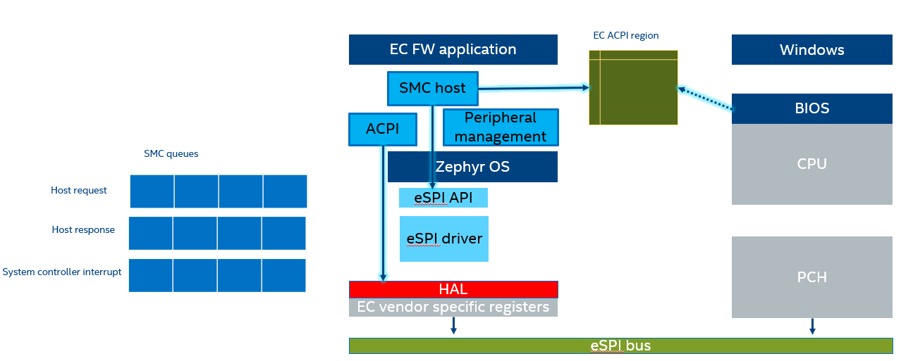
Implementation
The SMC host module is implemented as a cooperative thread that registers multiple callbacks within different modules to track event in the system.
The most relevant notifications are:
BIOS/EC commands
Host has sent data or command over eSPI bus using HW interface previously described.
Peripheral notifications
Used to be aware of any human interaction with the system that need to be notified to the BIOS/OS.
Host warning notifications
Host has issued a warning for an upcoming platform or host reset.
Queue Mechanism
The thread performs periodic checks on above notifications to handle all operations outside of ISR/callback context it follows same pattern as all other tasks where upon notification.
This module uses 2 queues one for incoming data and for outgoing data. A third queue is used to schedule system interrupt notifications towards BIOS/OS.
SCI Notifications
In several scenarios, EC is responsible to notify BIOS/OS about asynchronous event in the system, EC modules do enqueue different notifications.
Note
As mentioned before, in eSPI-enabled platform the register interface traffic is tunneled eSPI bus peripheral channel. Similarly, the System Controller Interrupt pin level is transmitted as eSPI virtual wire. Main implication is that SCI queue should be flushed whenever there is a platform reset event.
ACPI Region
ACPI standard supports multiple embedded controller in a system, each with its own addressable I/O space or EC ACPI region. Nevertheless, reference HW only has one instance. The region is defined in BIOS ACPI tables and this module defines a memory region that matches byte per byte the fields in that table.
BIOS runtime does implement ACPI methods that request EC read/write operations over this region. i.e. battery status.
Custom EC Commands
EC FW framework does extend the command interface defined in ACPI specification to enrich BIOS-EC interaction communication. These custom commands are defined under smchost_codes.h