Power Sequencing
This section describes the embedded controller firmware power sequencing module which handles platform out-of-reset sequencing and power management flows.
The embedded controller firmware follows Intel Platform design guide for all power sequencing timings and sequence. This module relies on platform events to keep track of these system transitions. These power signals either come from a host system (Intel SoC) or are generated by board circuitry.
Note
System in this case refers to either board, laptop or desktop running Windows OS, however some concepts are generic enough to be applicable to other OS.
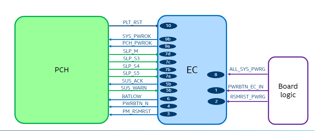
Power Signals
RSMRST#_PWRGD
Resume reset power good signal to the Embedded Controller hardware to indicate that main power rails on the board are stable, in response this module generates RSMRST output to PCH.
ALL_SYS_PWRGD
The all system power good input generated from board circuitry indicates to the Embedded Controller (EC) that SoC power rails are stable. Based on this the module will generate PCH_PWROK signal.
SLP_Sx#
SLP_S3#, SLP_S4# and SLP_S5# indicate that the host system is undergoing a system transition, in which case system is entering the specified sleep state indicated by the respective signal as defined in ACPI specification.
Note
The power signals can either be physical pins or virtual pins which are transmitted over the eSPI bus in the form of a virtual wire. The reference code assumes an eSPI-capable host. See Enhanced Serial Peripheral Interface specification
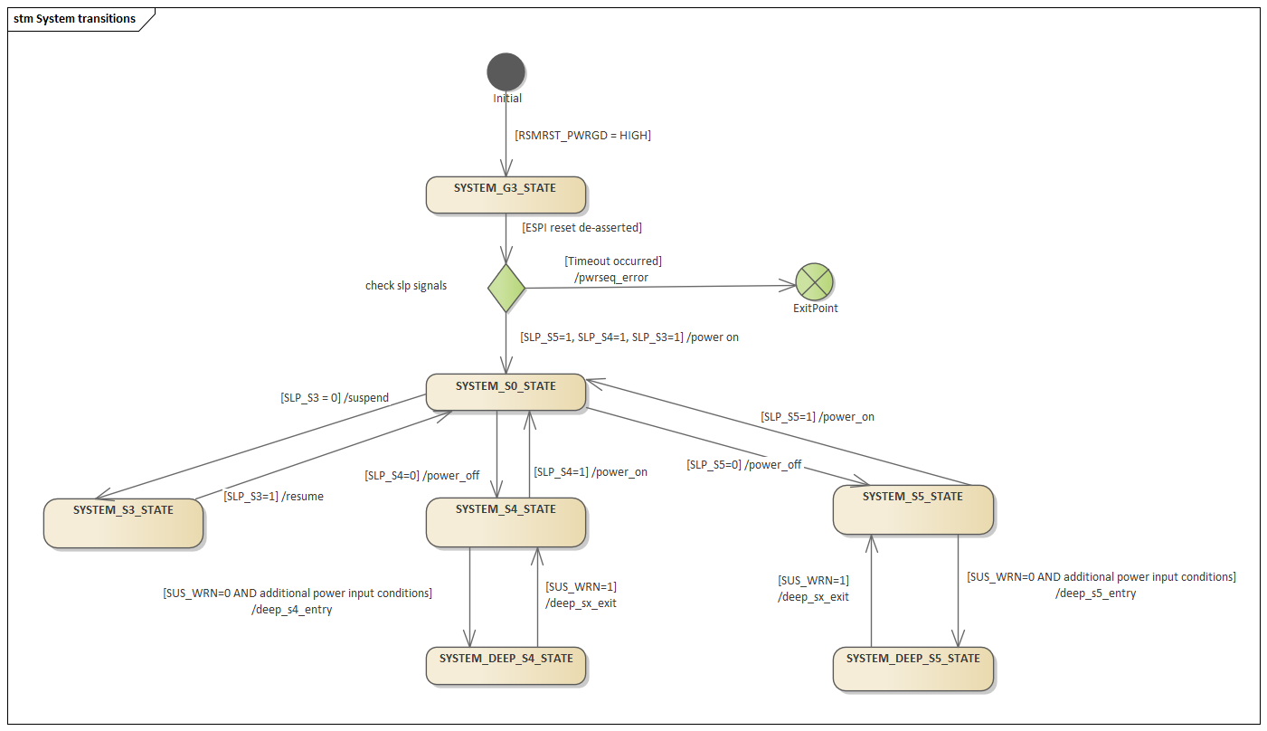
System transitions
This module main role is to handle system transitions between the global system states (Gx states) defined ACPI specification. The states apply to the system as a whole and are visible to the user.
Note
Windows OS is assumed in Intel TGL RVP, in which case Gx states map to user actions as follows: suspend (S3), hibernate (S4), shutdown (S5).
ACPI System Transitions
Flow for G3 to S0
Trigger events
Valid power button press
Platform sleep signal assertion
Actions
Check for any power button press
Check RSMRST_PWRGD input
Generate RSMRST#
Propagate power button status to PCH
Perform deep sleep exit handshake if supported a) PCH sends SUS_WRN virtual wire b) EC acknowledges by sending SUS_ACK virtual wire
Indicate if there is a valid power source or enough battery capacity to power up the system using PM_BATLOW signal.
Check power sequencing signals as described in the platform guide. These include SLP_S5, SLP_S4, SLP_S3 and SLP_M (sometimes referred as SLP_A).
Wait for ALL_SYS_PWRGD
Drive PCH_PWROK and if required by the system SYS_PWROK. Do refer to platform guide to see if this signal needs to be generated.
Wait for platform reset signal.
Flow for S0 to S3 (suspend)
Trigger events:
SLP_S3 signal assertion
Actions:
Turn off 7-segment display used for platform POST codes
Turn off system fan
Wait for event for resume
Flow for S3 to S0 (resume)
Trigger events:
SLP_S3 signal de-assertion
Power button
AC adaptor insertion or removal
Flow for S0 to S4/S5 (hibernate/shutdown)
Trigger events:
Respective sleep signal de-assertion (SLP_S4 or SLP_S5)
Actions:
Turn off 7-segment display used for platform POST codes
Turn off system fan
Reconfigure GPIOs for power saving
Remove PCH_PWROK signal
Flow for S5/S4 to S0
Trigger events:
Respective sleep signal de-assertion (SLP_S4 or SLP_S5)
Actions:
Turn on 7-segment display used for platform POST codes
Turn on system fan
Reconfigure GPIOs to previous state prior to transition.
Provide PCH_PWROK signal
Intel-specific Power Management Transitions
There are 2 additional low power states supported in some platforms which reduce power consumption further from S3/S4/S5 global states described in ACPI spec.
The implementation of these consider 2 different cases:
Embedded controller losing power after deep sleep entry
Embedded controller not losing power after deep sleep entry
For the case where Embedded Controller loses power during the transition, EC_DSx# signal is used keep EC on/off during system deep sleep.
Note
Deep sleep for S3 is not supported in this reference implementation.
Flow for S3/S4/S5 to deep sleep
Pre-condition:
System is already in S3/S4/S5
Triggers:
SUS_WRN power signal assertion is received.
Actions:
Module acknowledges notification by sending SUS_ACK
Module waits for PCH PM_SLP_SUS# assertion
Module asserts RSMRST#
Flow for deep sleep to S3/S4/S5
Triggers:
EC wakes via power button
Actions:
Module de-asserts RMSRST#
Module waits for SUS_WARN de-assertion.
Module acknowledges notification by sending SUS_ACK
Note
Once system is back to regular sleep states, EC FW waits for SLP_Sx# signals then follows normal S3 to S0 or S4/S5 to S0 flow.
Note
If EC HW main power rail was off during entry to deep sleep, EC FW will perform same flow G3 to S0 after SUS_WRN handshake describe earlier.
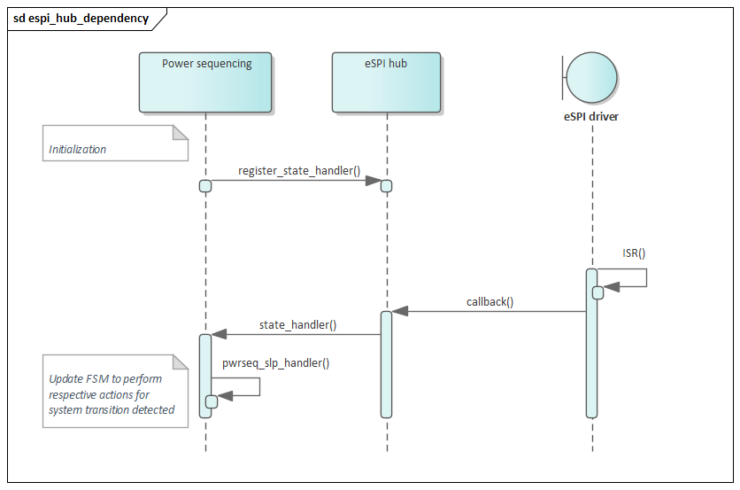
Implementation
This module uses a cooperative thread as described in the task handling section. The thread track overall system transitions then sleeps 10 ms before checking again for new events.
To track the different triggers the power sequencing module registers for notifications with the eSPI hub and whenever there is a relevant virtual wire event, the new system state is determined, and actions as described above are executed.
Note
Previous reference designs did rely on physical pins instead of eSPI Virtual Wires.
Timeout Mechanism
Each transition is triggered by a specific event and before the transition is completed, the module will check if certain conditions are met, if any each of these conditions is not fulfilled within a predetermined time interval the power sequencing will stop.
Such scenario is considered a power sequencing failure, so RSMRST# signal will be pulled LOW as required by platform design guide and a timeout code will be displayed in postcode display in the following format “ECNN”, where NN refers to a specific error code.
Variants Across Platforms
This module covers generic aspects of power sequencing, however for specific timings and/or signals not covered here refer to your Intel PCH specific Platform design guide.