Keyboard scan matrix
Introduction
A keyboard matrix is composed of a grid of wires representing rows and columns. These rows and columns are connected to an embedded controller(KSC) which continuously scans the state of all the grid. A circuit in the grid is closed when a key is pressed, and this is eventually sensed by the FW running in the EC. Once the row and column has been determined, the EC maps the grid coordinates to a scan code which is provided to the host as a set of bytes.
Implementation
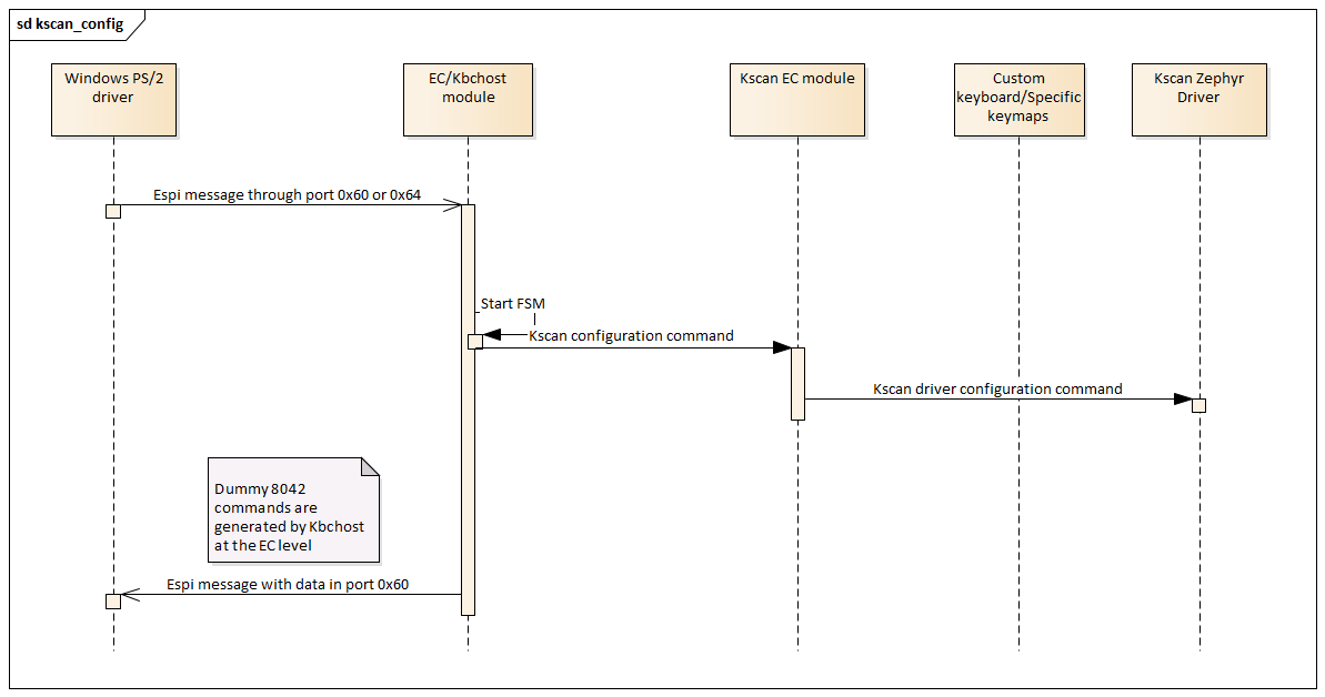
In this realization, state and data for a keyboard matrix are represented in the EC as an application module. This module depends on Keyboard System Controller Host to receive configuration commands and to sent keyboard events back to the host. Keyboard events are treated as if they were PS/2 keyboard events. There are a few configuration commands which are faked by kbchost since we want to let the initialization flow complete successfully. The image below illustrates components involved in the keyboard matrix configuration.
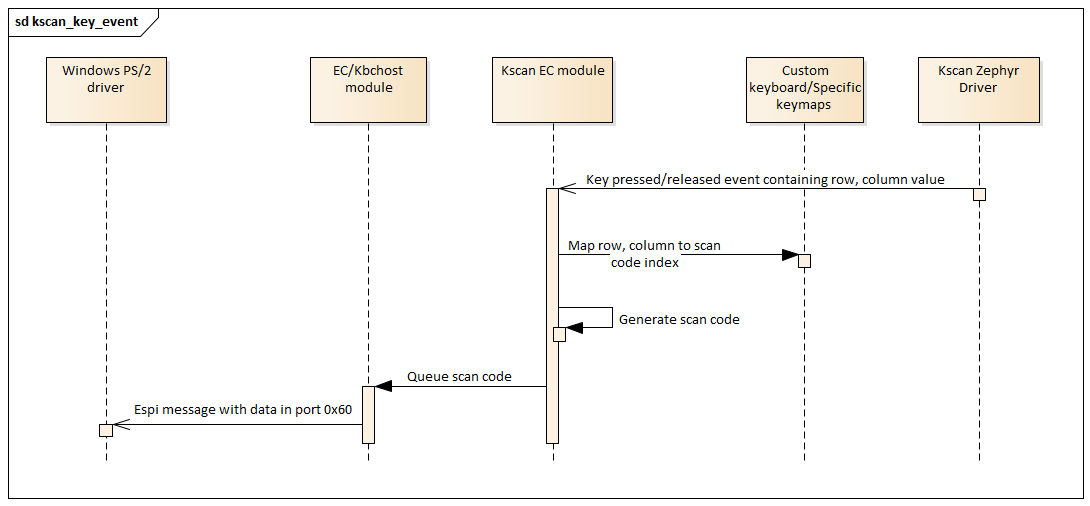
Keyboard events provide row and column data, so there isn’t any scanning performed by the keyboard matrix module since that is performed by the underlying Zephyr driver. The Zephyr driver also tracks which keys in the matrix are still pressed and which ones are being released. This data is relayed to the kscan application module in the form of callbacks. Once the callbacks are received, the application module translates grid coordinates to scan codes and queues them in the same queue used for sending PS/2 scan codes. See the image below for more details.
Note
The keyboard mapping (GTech) provided with the application cannot be connected to the modular card. The TGL board has a scan matrix ribbon connector at the bottom, but it is not mapped to the modular card which means it can’t also be used. More information will be provided later.

