This is a high-level description of how PCIe is implemented in Simics. If you write your device in DML, most of the details below are automatically handled by the DML templates.
The Simics PCIe modeling framework provides the ability to model
A PCIe device must implement the pcie_device interface. This
interface is used to indicate when the device is connected,
disconnected, and to signal a hot reset.
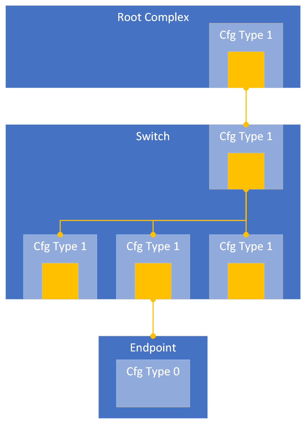
An RC, Switch or other bridges, must use helper-objects of the class
pcie-downstream-port to simulate the downstream port(s). Each port
facing downstream, i.e. each Virtual PCIe-PCIe bridge in the RC or
Switch (represented by a Type 1 Configuration Header), should have a
pcie-downstream-port. Each downstream port can connect to one or
several (external) PCIe devices. The upstream-facing port of a Switch
should have a pcie-downstream-port with the (internal) Virtual
PCIe-PCIe bridge(s) connected as devices. The below image illustrates
a sample PCIe hierarchy in Simics, yellow boxes represent
pcie-downstream-ports.
The pcie-downstream-port routes messages and manages the Config, IO
and Memory address spaces for its connected downstream devices. There
is a translator-port downstream which receives downstream
transactions and redirects them to the downstream devices connected to
it. There are also specialized translator-ports cfg, msg, io,
and mem which can be used to send transactions of their specific type.
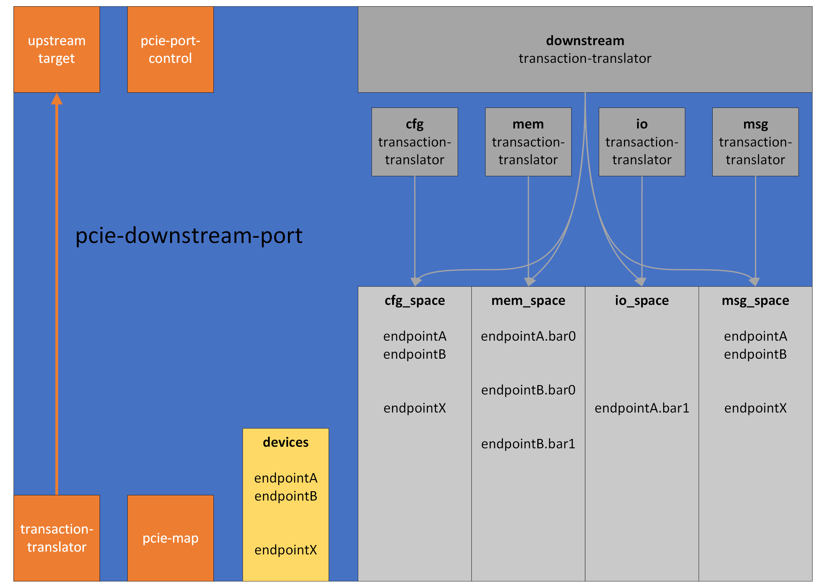
The interface pcie_port_control is implemented by the
pcie-downstream-port, it is used by whoever owns the port to configure
it, and to signal hot reset. The pcie-downstream-port also implements
the pcie_map interface, which the Endpoints below it use to claim
ranges in the downstream address space (e.g. Memory and I/O BARs), and
add (virtual) functions. An endpoint starts an upstream transaction by
issuing it to its connected pcie-downstream-port
Endpoints issue upstream transactions through the pcie-downstream-port
object of the RC/Switch to which they are connected. The
pcie-downstream-port acts as a translator and will direct all upstream
transactions to its upstream_target, typically the host memory in
case of an RC, or the upstream target in case of a Switch.
Endpoints must add their functions and map other resources such as
Memory and I/O BARs (as configured in the relevant registers of the
Type 0 Configuration Header). This is done through the pcie_map
interface of the pcie-downstream-port object to which they are
connected.
Switches have an upstream port which is connected to the
pcie-downstream-port of either a Root Complex or another Switch. As
the downstream port(s) of the Switch are configured, they must map the
resources of these ports in the pcie-downstream-port of the RC/Switch
to which they are connected. For example, the Message and
Configuration range bounded by secondary and subordinate bus
registers, as well as the Memory and IO ranges bounded by base and
limit registers.