It is not uncommon for a device to be able to act as bus-master, reading and writing memory as it pleases. There may be several reasons why direct memory access (DMA) is supported by a device. One reason could be that the device's DMA capability may offload the CPU core by transferring large chunks of memory on the behalf of software. Another scenario is when a device has to be programmed. If the device supports many options, writing to its registers may be slow, since they usually exist in cache-inhibited space. Using DMA all required information can be written to a descriptor in memory and the address to that descriptor can then be written to a register in the device, using a single (slow) register write. The device is then able to fetch the required information from main memory on its own, offloading the CPU cores. This section will demonstrate how to write device models that support DMA.
In this section it will be described how to create a model of a DMA device that can be used to autonomously copy data from one area of the memory to another. By reading this section you will learn how to:
As always when starting out to develop a new device model, it is necessary to prepare your project for the new device. To do this, issue the following command:
project$ ./bin/project-setup --device=my-dma-device
This will create skeleton files for a new device, my_dma_device. The relevant files will show up in [project]/modules/my-dma-device/. At this point it should be possible to type make in the project directory to build the skeleton device. The bulk of the device's code will go in the file my-dma-device.dml. Examine this file, it should look something like.
dml 1.4;

device my_dma_device;
param desc = "name of device";

param documentation = "Longer description that will appear in the help";

import "utility.dml";

bank regs {
    param register_size = 4;

    register counter @ 0x00 "A simple counter.";
}

bank regs {
    register counter {

    }
}
The skeleton code implements a simple counter. Since the DMA device does not have this functionality it can be removed. The post_init method is not going to be used either, so get rid of that as well. The description param desc and short documentation param documentation should be written. The device code should now look something like:
dml 1.4;

device my_dma_device;
param desc = "example DMA device";

param documentation =
    "Example of a DMA device supporting contiguous memory or scatter-gather "
    + "lists. The device has a controllable throughput (words per second) "
    + "and supports either polling mode or interrupt based signalling upon "
    + "DMA completion.";

import "utility.dml";


bank regs {
    param register_size = 4;

}
This device now has a single (empty) register bank with 4-byte registers. The DMA device modeled in this section has three registers, DMA_control, DMA_source and DMA_dest. The DMA_source and DMA_dest registers will hold the source and destination address of the DMA transfer. The DMA_control register is used to issue control commands to the DMA engine and to receive the device's status. Add the three registers to the bank.
bank regs {
    param register_size = 4;
    register DMA_control @ 0x00 "Control register";
    register DMA_source  @ 0x04 is (unimpl) "Source address";
    register DMA_dest    @ 0x08 is (unimpl) "Destination address";
}
Compile the device again and start a new Simics session. It should now be possible to instantiate the DMA device.
project$ ./simics
simics> @SIM_create_object ("my_dma_device", "mydma")
simics> help mydma
Class my_dma_device

  Provided by
    my-dma-device

  Interfaces Implemented
    conf_object, log_object

  Ports
    regs (io_memory), regs (int_register)

  Description
    Example of a DMA device supporting contiguous memory or scatter-gather
    lists. The device has a controllable throughput (words per second) and
    supports either polling mode or interrupt based signalling upon DMA
    completion.


Command List

  Commands defined by interface conf_object
    get-attribute-list, get-interface-list, get-interface-port-list,
    list-attributes, list-interfaces, log, log-group, log-level, log-size,
    log-type

  Commands
    info                print information about the device
    status              print status of the device


Attributes

  regs_DMA_control, regs_DMA_dest, regs_DMA_source

simics>
Note that attributes for the registers are created automatically.
The DMA_control register is divided into a number of fields. Add a bank definition with the DMA_control register and explicitly include those fields.
bank regs {
    register DMA_control {
        field EN   @ [31]  is (unimpl) "Enable DMA";
        field SWT  @ [30]  is (unimpl) "Software Transfer Trigger";
        field ECI  @ [29]  is (unimpl) "Enable Completion Interrupt";
        field TC   @ [28]  is (read_only)     "Transfer complete";
        field SG   @ [27]  is (unimpl) "Scatter-gather list input";
        field ERR  @ [26] "DMA transfer error";
        field TS   @ [15:0] "Transfer size (32-bit words)";
    }
}
Now that the device's register map has been defined it is time to start implementing its behavior. A DMA transfer of TS words from DMA_source to DMA_dest is triggered when writing a 1 to the SWT field of DMA_control, if DMA is enabled by setting the EN bit. Once transfer is completed the DMA device will notify software by setting the TC bit and, if interrupts are enabled (ECI bit set), the DMA device will trigger an interrupt. Using interrupts alleviates software from the burden of polling the DMA device's control register. The SG field will be described in section 18.3 when dealing with descriptors and the SG field can be ignored for now.
Since the DMA transfer is initiated as a consequence of writing the SWT bit of the control register one way of initiating the transaction is to overload the write_register method of the DMA_control register.
bank regs {
    register DMA_control {
        field EN   @ [31]  "Enable DMA";
        field SWT  @ [30]  "Software Transfer Trigger";
        field ECI  @ [29]  is (unimpl) "Enable Completion Interrupt";
        field TC   @ [28]  is (read_only)     "Transfer complete";
        field SG   @ [27]  is (unimpl) "Scatter-gather list input";
        field ERR  @ [26] "DMA transfer error";
        field TS   @ [15:0] "Transfer size (32-bit words)";

        method write_register(uint64 value, uint64 enabled_bytes, void *aux) {
            default(value, enabled_bytes, aux);
            do_dma_transfer();
        }
    }
    method do_dma_transfer() {
        if (DMA_control.SWT.val == 0)
            return; // No need to do anything if we are not asked by software

        // Software asked us to initiate a DMA transfer
        if(DMA_control.EN.val == 0) {
            // enable bit not set, so we cannot transfer
            log info, 2: "EN bit not set, SWT = 1 has no effect";
            return;
        }

        log info, 3: "EN bit set, SWT written, initiating DMA";
        log info, 3: "Transferring %d 32-bit words from 0x%x to 0x%x",
            DMA_control.TS.val, DMA_source.val, DMA_dest.val;

        complete_dma();
    }

    method complete_dma() {
        log unimpl, 1: "DMA transfer completion not implemented.";
    }
}
Now that the basic logic is in place the only thing left is to actually transfer the data. In order to do this the DMA device must have a connection to the memory-space it is to operate in. Add this connection.
import "utility.dml";
import "simics/devs/memory-space.dml";

// Memory-space connection for DMA work
connect target_mem_space {
    param documentation =
        "The memory space on which the DMA engine operates. Data will be "
        + "read from and copied to the memory associated with this memory "
        + "space.";
    param configuration = "required";
    interface memory_space;
}
To make DMA operation more convenient two utility methods are also added, read_mem and write_mem. These methods reads or writes an array of bytes from or to target memory. Think of them as a memcpy between host and target.
// Read len bytes of target memory from the address src in the memory
// $target_mem_space. The result is put in memory pointed to by dst,
// which must be large enough to hold at least len bytes. If a memory
// access error occurs this method will print an error message and
// throw an exception.
method read_mem(void *dst,
                physical_address_t src,
                physical_address_t len) throws {
    local exception_type_t exc;
    exc = target_mem_space.memory_space.access_simple(dev.obj,
                                                src,
                                                dst,
                                                len,
                                                Sim_RW_Read,
                                                Sim_Endian_Target);

    if (exc != Sim_PE_No_Exception) {
        log error: "an error occurred when reading target memory";
        throw;
    }
}

// Write len bytes to target memory from the memory pointed to by
// src. The data is written to the memory space $target_mem_space at
// address dst. If a memory access error occurs this method will
// print an error message and throw an exception.
method write_mem(physical_address_t dst,
                 const void *src,
                 physical_address_t len) throws {
    local exception_type_t exc;
    exc = target_mem_space.memory_space.access_simple(dev.obj,
                                                dst,
                                                cast(src, uint8*),
                                                len,
                                                Sim_RW_Write,
                                                Sim_Endian_Target);

    if (exc != Sim_PE_No_Exception) {
        log error: "an error occurred when writing to target memory";
        throw;
    }
}


bank regs {
Now the time has come to implement the actual transferring of bytes, the main purpose of the DMA device.
    method do_dma_transfer() {
        if (DMA_control.SWT.val == 0)
            return; // No need to do anything if we are not asked by software

        // Software asked us to initiate a DMA transfer
        if(DMA_control.EN.val == 0) {
            // enable bit not set, so we cannot transfer
            log info, 2: "EN bit not set, SWT = 1 has no effect";
            return;
        }

        log info, 3: "EN bit set, SWT written, initiating DMA";
        log info, 3: "Transferring %d 32-bit words from 0x%x to 0x%x",
            DMA_control.TS.val, DMA_source.val, DMA_dest.val;

        local uint18 count = DMA_control.TS.val * 4;
        try {
            // Copy the memory block
            local uint8 buf[count];
            read_mem(buf, DMA_source.val, count);
            write_mem(DMA_dest.val, buf, count);
        } catch {
            log error: "DMA memory access failed";
            return;
        }

        complete_dma();
    }

    method complete_dma() {
        // Log that completion is done
        log info, 2: "DMA transfer completed";

        // clear SWT bit, update TS
        DMA_control.SWT.val = 0;
        DMA_control.TS.val = 0;
        DMA_control.TC.val = 1;
    }
}
Since DMA transfer should now be operational it is no longer appropriate to mark the source and destination registers as unimplemented.
    register DMA_source  @ 0x04 "Source address";
    register DMA_dest    @ 0x08 "Destination address";
After adding the target_mem_space connector the device model can no longer be instantiated on its own. To test the device start the sample machine in [project]/targets/qsp-x86/firststeps.simics.
The object of the memory-space class corresponding to the main memory of this machine is called board.mb.phys_mem. One can get insight into the machine's memory map with the info command of the CPU object and the <memory-space>.map command of the memory objects. To get the DMA device working it is necessary to map it into the memory-space.
project$ ./simics ./targets/qsp-x86/firststeps.simics

simics> board.mb.cpu0.core[0][0].info
Information about board.mb.cpu0.core[0][0] [class x86QSP1]
==========================================================

                     VMP status : Enabled
                JIT compilation : Enabled
                Clock frequency : 2000 MHz
                            CPI : 1.00
                Physical memory : board.mb.cpu0.mem[0][0]
                           Cell : board.cell
To get the system to initialize the DDR memory the simulation has to run for a short while.
simics> run 2 s

simics> board.mb.phys_mem.map
┌───────────┬────────────────────────────┬──┬───────────┬───────────┬──────┬────┬─────┬────┐
│       Base│Object                      │Fn│     Offset│     Length│Target│Prio│Align│Swap│
├───────────┼────────────────────────────┼──┼───────────┼───────────┼──────┼────┼─────┼────┤
│        0x0│board.mb.dram_space         │  │        0x0│    0xa0000│      │   0│     │    │
│   0x100000│board.mb.dram_space         │  │   0x100000│ 0xdff00000│      │   0│     │    │
│0x100000000│board.mb.dram_space         │  │0x100000000│0x100000000│      │   0│     │    │
│  -default-│board.mb.nb.pci_bus.port.mem│  │        0x0│           │      │    │     │    │
└───────────┴────────────────────────────┴──┴───────────┴───────────┴──────┴────┴─────┴────┘

simics> @SIM_create_object("my_dma_device", "mydma", target_mem_space=
conf.board.mb.phys_mem)

simics> board.mb.phys_mem.add-map mydma.bank.regs  0x250000000 0xc
Mapped 'mydma.bank.regs' in 'board.mb.phys_mem' at address 0x250000000.
Make sure the device was correctly mapped by examining the memory map of the board.mb.phys_mem memory-space.
simics> board.mb.phys_mem.map
┌───────────┬────────────────────────────┬──┬───────────┬───────────┬──────┬────┬─────┬────┐
│       Base│Object                      │Fn│     Offset│     Length│Target│Prio│Align│Swap│
├───────────┼────────────────────────────┼──┼───────────┼───────────┼──────┼────┼─────┼────┤
│        0x0│board.mb.dram_space         │  │        0x0│    0xa0000│      │   0│     │    │
│   0x100000│board.mb.dram_space         │  │   0x100000│ 0xdff00000│      │   0│     │    │
│0x100000000│board.mb.dram_space         │  │0x100000000│0x100000000│      │   0│     │    │
│0x250000000│mydma.bank.regs             │  │        0x0│        0xc│      │   0│    8│    │
│  -default-│board.mb.nb.pci_bus.port.mem│  │        0x0│           │      │    │     │    │
└───────────┴────────────────────────────┴──┴───────────┴───────────┴──────┴────┴─────┴────┘
To test the device it is possible to trigger a DMA transfer from within Simics by manually writing to the appropriate registers.
Set the source register to 0x20000 by writing to the physical memory at address 0x250000004. Remember that the DMA device was previously mapped at offset 0x250000000 in the physical memory and that the source register is at offset 4 in the regs bank of the device.
simics> board.mb.phys_mem.write 0x250000004 0x20000
Now examine the register's value with print-device-regs:
simics> print-device-reg-info mydma.bank.regs.DMA_source
Source address [mydma.bank.regs.DMA_source]

                   Bits : 32
                 Offset : 0x4
                  Value : 131072 (0x00020000)

Bit Fields:
    DMA_source @ [31:0] : 00000000000000100000000000000000
Note that the write and read commands by default use the current processor endianness. In our case the device and the sample machine use little endian byte ordering so that matches. But little endian devices can (and do) exist on big endian machines, and vice versa. So if endianness between processor and device does not match you can use the -l (little) and -b (big) flags to select the endianness of the access. For example, the below access would use big endian byte order and hence the value - as understood by the little endian device - does not match what was written.
simics> board.mb.phys_mem.write 0x250000004 0x20000 -b
simics> print-device-reg-info mydma.bank.regs.DMA_source
Source address [mydma.bank.regs.DMA_source]

                   Bits : 32
                 Offset : 0x4
                  Value : 512 (0x00000200)

Bit Fields:
    DMA_source @ [31:0] : 00000000000000000000001000000000
Assuming the device should actually be big endian it is a simple matter to convert it. All that is required is to tell DML to use big endian byte order.
import "utility.dml";
import "simics/devs/memory-space.dml";

param byte_order = "big-endian";

// Memory-space connection for DMA work
connect target_mem_space {
    param documentation =
        "The memory space on which the DMA engine operates. Data will be "
        + "read from and copied to the memory associated with this memory "
        + "space.";
    param configuration = "required";
    interface memory_space;
}
Recompile the device and repeat the above steps for big endian accesses. You will notice that the device now interprets the data in its registers in big endian byte order.
project$ make
=== Building module "my_dma_device" ===
[…]

project$ ./simics ./targets/qsp-x86/firststeps.simics

simics> c 2_000_000

simics> @SIM_create_object("my_dma_device", "mydma",
	        [["target_mem_space", conf.board.mb.phys_mem]])

simics> board.mb.phys_mem.add-map mydma.bank.regs  0x250000000 0xc
simics> board.mb.phys_mem.write 0x250000004 0x20000 -b
simics> print-device-reg-info mydma.bank.regs.DMA_source
Source address [mydma.bank.regs.DMA_source]

                   Bits : 32
                 Offset : 0x4
                  Value : 131072 (0x00020000)

Bit Fields:
    DMA_source @ [31:0] : 00000000000000100000000000000000
simics> board.mb.phys_mem.write 0x250000008 0x30000 -b
simics> print-device-reg-info mydma.bank.regs.DMA_dest
Destination address [mydma.bank.regs.DMA_dest]

                 Bits : 32
               Offset : 0x8
                Value : 196608 (0x00030000)

Bit Fields:
    DMA_dest @ [31:0] : 00000000000000110000000000000000
Now transfer 16 words of data by writing a control word to the DMA device.
simics> mydma.log-level 4
[mydma] Changing log level: 1 -> 4

simics> $cw = 0xc0000010
simics> board.mb.phys_mem.write 0x250000000 $cw -b
[mydma info] Write to register regs.DMA_control <- 0xc0000010
[mydma.bank.regs info] EN bit set, SWT written, initiating DMA
[mydma.bank.regs info] Transferring 16 32-bit words from 0x20000 to 0x30000
[mydma.bank.regs info] DMA transfer completed
simics>
Note that the first thing done is to raise the log-level of the DMA device to 4 so that it is possible to track the execution path. Now the basic DMA device is completed. The following sections will demonstrate how to make the DMA transfer appear to take (virtual) time, how to generate interrupts on completion and how to use layouts to transfer data from a scatter-gather list. The full source for the DMA device used throughout this section is listed below.
dml 1.4;

device my_dma_device;
param desc = "example DMA device";

param documentation =
    "Example of a DMA device supporting contiguous memory or scatter-gather "
    + "lists. The device has a controllable throughput (words per second) "
    + "and supports either polling mode or interrupt based signalling upon "
    + "DMA completion.";

import "utility.dml";
import "simics/devs/memory-space.dml";

param byte_order = "big-endian";

// Memory-space connection for DMA work
connect target_mem_space {
    param documentation =
        "The memory space on which the DMA engine operates. Data will be "
        + "read from and copied to the memory associated with this memory "
        + "space.";
    param configuration = "required";
    interface memory_space;
}

bank regs {
    param register_size = 4;
    register DMA_control @ 0x00 "Control register";
    register DMA_source  @ 0x04 "Source address";
    register DMA_dest    @ 0x08 "Destination address";
}

// Read len bytes of target memory from the address src in the memory
// $target_mem_space. The result is put in memory pointed to by dst,
// which must be large enough to hold at least len bytes. If a memory
// access error occurs this method will print an error message and
// throw an exception.
method read_mem(void *dst,
                physical_address_t src,
                physical_address_t len) throws {
    local exception_type_t exc;
    exc = target_mem_space.memory_space.access_simple(dev.obj,
                                                src,
                                                dst,
                                                len,
                                                Sim_RW_Read,
                                                Sim_Endian_Target);

    if (exc != Sim_PE_No_Exception) {
        log error: "an error occurred when reading target memory";
        throw;
    }
}

// Write len bytes to target memory from the memory pointed to by
// src. The data is written to the memory space $target_mem_space at
// address dst. If a memory access error occurs this method will
// print an error message and throw an exception.
method write_mem(physical_address_t dst,
                 const void *src,
                 physical_address_t len) throws {
    local exception_type_t exc;
    exc = target_mem_space.memory_space.access_simple(dev.obj,
                                                dst,
                                                cast(src, uint8*),
                                                len,
                                                Sim_RW_Write,
                                                Sim_Endian_Target);

    if (exc != Sim_PE_No_Exception) {
        log error: "an error occurred when writing to target memory";
        throw;
    }
}

bank regs {
    register DMA_control {
        field EN   @ [31]  "Enable DMA";
        field SWT  @ [30]  "Software Transfer Trigger";
        field ECI  @ [29]  is (unimpl) "Enable Completion Interrupt";
        field TC   @ [28]  is (read_only)     "Transfer complete";
        field SG   @ [27]  is (unimpl) "Scatter-gather list input";
        field ERR  @ [26] "DMA transfer error";
        field TS   @ [15:0] "Transfer size (32-bit words)";

        method write_register(uint64 value, uint64 enabled_bytes, void *aux) {
            default(value, enabled_bytes, aux);
            do_dma_transfer();
        }
    }

    method do_dma_transfer() {
        if (DMA_control.SWT.val == 0)
            return; // No need to do anything if we are not asked by software

        // Software asked us to initiate a DMA transfer
        if(DMA_control.EN.val == 0) {
            // enable bit not set, so we cannot transfer
            log info, 2: "EN bit not set, SWT = 1 has no effect";
            return;
        }

        log info, 3: "EN bit set, SWT written, initiating DMA";
        log info, 3: "Transferring %d 32-bit words from 0x%x to 0x%x",
            DMA_control.TS.val, DMA_source.val, DMA_dest.val;

        local uint18 count = DMA_control.TS.val * 4;
        try {
            // Copy the memory block
            local uint8 buf[count];
            read_mem(buf, DMA_source.val, count);
            write_mem(DMA_dest.val, buf, count);
        } catch {
            log error: "DMA memory access failed";
            return;
        }

        complete_dma();
    }

    method complete_dma() {
        // Log that completion is done
        log info, 2: "DMA transfer completed";

        // clear SWT bit, update TS
        DMA_control.SWT.val = 0;
        DMA_control.TS.val = 0;
        DMA_control.TC.val = 1;
    }
}
Software often expects operations such as DMA transfers to take some amount of time. Some device drivers even rely on this in order to work properly. In order to simulate the passage of time in a device it is necessary to estimate how long an operation should take and to delay the effects by that amount. The DMA device will use a simple algorithm to compute the time a DMA transfer should take. The time will be proportional to the number of words copied. The after statement in DML is the easiest way to delay the call to complete_dma. In this example the DMA device will appear to transfer one million words per second since the delay is set to 1 ms per word. The after statement posts an event, which when executed calls the method complete_dma.
    method do_dma_transfer() {
        if (DMA_control.SWT.val == 0)
            return; // No need to do anything if we are not asked by software

        // Software asked us to initiate a DMA transfer
        if(DMA_control.EN.val == 0) {
            // enable bit not set, so we cannot transfer
            log info, 2: "EN bit not set, SWT = 1 has no effect";
            return;
        }

        log info, 3: "EN bit set, SWT written, initiating DMA";
        log info, 3: "Transferring %d 32-bit words from 0x%x to 0x%x",
            DMA_control.TS.val, DMA_source.val, DMA_dest.val;

        local uint18 count = DMA_control.TS.val * 4;
        try {
            // Copy the memory block
            local uint8 buf[count];
            read_mem(buf, DMA_source.val, count);
            write_mem(DMA_dest.val, buf, count);
        } catch {
            log error: "DMA memory access failed";
            return;
        }
        after 1.0e-6 * count / 4.0 s: complete_dma();
    }
Test the device again
simics> c 2_000_000

simics> @SIM_create_object("my_dma_device", "mydma",
	  [["target_mem_space", conf.board.mb.phys_mem],
	  ["queue", conf.board.mb.soc.cpu[0]]])

simics> board.mb.phys_mem.add-map mydma.bank.regs  0x250000000 0xc
Mapped 'mydma.bank.regs' in 'board.mb.phys_mem' at address 0x250000000.
simics> board.mb.phys_mem.write 0x250000004 0x20000 -b
simics> board.mb.phys_mem.write 0x250000008 0x30000 -b
simics> $cw = 0xc0000010

simics> mydma.log-level 4
[mydma] Changing log level: 1 -> 4

simics> board.mb.phys_mem.write 0x250000000 $cw -b
[mydma info] Write to register regs.DMA_control <- 0xc0000010
[mydma.bank.regs info] EN bit set, SWT written, initiating DMA
[mydma.bank.regs info] Transferring 16 32-bit words from 0x20000 to 0x30000
There are a few differences compared to the previous time the device model was tested. First the queue attribute of the device is set to the CPU. A time queue is required for a device that post events. If the queue attribute had not been set it had been forced to the CPU anyway but an error message would have been generated. The other difference is that the "DMA transfer completed" message no longer appears. This is because the simulation is currently not running and the DMA transfer is supposed to take some time.
It is possible to examine the event queue using the peq command. It is possible to see that there is an event complete_dma pending for the mydma object.
simics> peq
┌────────────┬────────────────────────┬─────────────────┐
│   Cycle    │         Object         │   Description   │
├────────────┼────────────────────────┼─────────────────┤
│       32000│mydma                   │regs.complete_dma│
│     1600000│board.mb.sb.uhci[0]     │frame_update     │
│     1600000│board.mb.sb.uhci[1]     │frame_update     │
│     1600000│board.mb.sb.uhci[2]     │frame_update     │
│     1600000│board.mb.sb.uhci[3]     │frame_update     │
│     1600000│board.mb.sb.uhci[4]     │frame_update     │
│     1600000│board.mb.sb.uhci[5]     │frame_update     │
│  9371537749│board.mb.sb.lpc         │pm1_ovf          │
│129169947853│board.mb.cpu0.apic[0][0]│timer interrupt  │
└────────────┴────────────────────────┴─────────────────┘
Continue the simulation for a few steps and the DMA transfer will complete.
simics> c 220000
[mydma.bank.regs info] DMA transfer completed
simics>
It is probably better to allow the user to determine the transfer rate of the DMA device. This is easily accomplished by adding an attribute for the transfer rate.
// Timing parameter
attribute throttle is double_attr {
    is init;
    method init() {
        val = 1e-6; // a really slow DMA device
    }

    param documentation =
        "Delay in seconds per 32-bit word of memory copied, default is 1μs.";
    param configuration = "optional";
}
Then update the after line in do_dma_transfer method to use this attribute to calculate the transfer delay.
after throttle.val * count / 4.0 s: complete_dma();
It is also a good idea to supply a reasonable default value for the transfer rate. This can be done by instantiating the init template and providing the init method, which is called before all attributes are initialized by loading a checkpoint or configuration.
Since DMA transfers now take some time, software will have to poll the TC bit of the DMA_control register in order to determine when the DMA transfer is done. This is inefficient and it would be better if the DMA device could notify software that it is done through some mechanism that does not require polling. The next section will demonstrate how to improve the DMA device so that it will interrupt the processor when the transfer is completed.
To avoid the situation where software has to poll hardware during lengthy operation interrupts can be used to notify software that an interesting event has taken place. This section demonstrates how to deliver an interrupt to a CPU core when DMA transfer is completed.
To be able to interrupt the CPU the device must have a connection to it. The CPUs in Simics support the signal interface that can be used to signal an interrupt. Add a new connection to the device that should receive interrupts (this is not necessarily the CPU core).
// CPU connection for interrupting
connect intr_target {
    param documentation =
        "Interrupt target port to signal on DMA interrupts.";
    param configuration = "required";
    interface signal;
}
Once again it will be necessary to supply additional parameters when instantiating the mydma object. This time the device's intr_target attribute is set to [conf.board.mb.cpu0.core[0][0], "NMI"], connecting the intr_target connection to the external interrupt port on the CPU.
simics> @SIM_create_object("my_dma_device", "mydma",
          [["target_mem_space", conf.board.mb.phys_mem],
          ["queue", conf.board.mb.cpu0.core[0][0]],
          ["intr_target", [conf.board.mb.cpu0.core[0][0], "NMI"]]]
Add a saved variable to keep track if an interrupt has been raised or not.
// Tracks if interrupts are posted.
saved bool DMA_interrupt_posted;
Next, add the code that will raise the interrupt once the transfer is completed to the end of complete_dma.
        DMA_control.TS.val = 0;
        DMA_control.TC.val = 1;

        // raise interrupt towards CPU
        if(DMA_control.ECI.val == 0) {
            log info, 3: "ECI is zero, no interrupt raised";
            return;
        }

        log info, 3: "raising interrupt signal";
        intr_target.signal.signal_raise();

        // remember that we raised it
        DMA_interrupt_posted = true;
Now the device can interrupt the CPU to inform it that DMA transfer has completed. However, once raised the signal will stay asserted forever. The software needs a mechanism for acknowledging receipt of the interrupt. This mechanism is implemented using the TC (transfer complete) bit in this particular DMA device. First change the TC field from read-only to read-write and then implement its semantics in the write method. Since interrupt functionality is now implemented also change the ECI field from unimplemented.
    register DMA_control {
        field EN   @ [31] "Enable DMA";
        field SWT  @ [30] "Software Transfer Trigger";
        field ECI  @ [29]  "Enable Completion Interrupt";
        field TC   @ [28] "Transfer complete" {
            // Set to 1 when transfer completed by device itself.
            // Clear by writing a zero.
            // If interrupts are enabled and interrupt status is one
            // also clear the interrupt in the processor.
            is write;
            method write(uint64 value) {
                if (value != 0) {
                    log spec_viol: "write one to TC - ignored";
                    return;
                }

                if (this.val == 0) // Already cleared
                    return;

                log info, 3: "write zero to TC - clearing TC";
                this.val = 0;

                if (!DMA_interrupt_posted)
                    return;

                log info, 3: "also clearing interrupt on CPU";
                DMA_interrupt_posted = false; // remember cleared
                intr_target.signal.signal_lower();
            }
        }
        field SG   @ [27]  is (unimpl) "Scatter-gather list input";
        field ERR  @ [26] "DMA transfer error";
        field TS   @ [15:0] "Transfer size (32-bit words)";
        method write_register(uint64 value, uint64 enabled_bytes, void *aux) {
            default(value, enabled_bytes, aux);
            do_dma_transfer();
        }
Now the DMA device is completed, except for the field SG which is still marked as unimplemented. The next section will finalize the DMA device by adding support for reading data from a scatter-gather list when performing the copy operation.
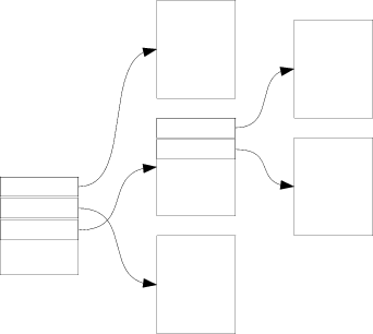
This section will show how layouts can be used to help with parsing descriptors that reside in target memory. A data structure known as scatter-gather list will be traversed during DMA copy operation. In a scatter-gather list data is spread out over several blocks. These blocks can be of two types, data blocks and extension blocks. A data block is simply a chunk of application specific data while the extension blocks contains references to other blocks. Extension blocks are always referenced from the last row in another extension block. An example of a scatter-gather data structure is shown in Figure 4.
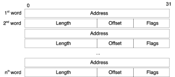
The layout of an extension block is shown in Figure 5. The individual fields are described below:
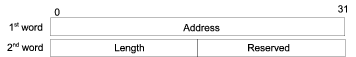
When using scatter-gather mode the DMA_source register contains the address of a scatter-gather head block. The head block is illustrated in Figure 6. The head block points to the first scatter gather block, which is always an extension block. The length field is the length of valid data in the first extension block.
The first step towards supporting scatter-gather lists is to break out the part of the code in do_dma_transfer that actually does the copying and put that in a method of its own.
    method copy_contiguous(physical_address_t dst,
                          physical_address_t src,
                          uint18 count) throws {
        local uint8 buf[count];
        read_mem(buf, src, count);
        write_mem(dst, buf, count);
    }
Next define two new layout types corresponding to the descriptors. Note that "big-endian" byte order is used since the target machine is big endian. Layouts makes it possible to conveniently access target memory regardless of the host's and target's byte order. Refer to the DML 1.4 Reference Manual for more details on layouts.
typedef layout "big-endian" {
    uint32 addr;
    uint16 len;
    uint16 reserved;
} sg_list_head_t;

typedef layout "big-endian" {
    uint32 addr;
    uint16 len;
    uint8 offset;
    bitfields 8 {
        uint1 ext @ [0:0];
    } flags;
} sg_list_block_row_t;
Add a method that steps one step forward in the scatter-gather list, either going to the next row of the current block or following an extension block to the next block.
    // next_row - Returns the address to next row to be processed.
    // end_addr is the address after the end of the block, if this address
    // is reached the transaction should have finished
    method next_row(physical_address_t addr, physical_address_t end_addr)
        -> (physical_address_t, physical_address_t,
            bool) throws /* next_addr, next_end_addr, finished */ {
        local physical_address_t next_addr;
        local physical_address_t next_end_addr;
        local bool finished;
        local sg_list_block_row_t block_row;
        read_mem(&block_row, addr, sizeof block_row);
        if (block_row.flags.ext) {
            next_addr = block_row.addr + block_row.offset;
            next_end_addr = next_addr + block_row.len;
        } else {
            next_addr = addr + sizeof block_row;
            next_end_addr = end_addr;
        }
        finished = next_addr == end_addr;
        return (next_addr, next_end_addr, finished);
    }
Now implement a new copy-method that copies data contained in a scatter-gather list. This method should use the next_row method to advance in the scatter-gather list. The method should return the number of bytes copied so these can be used to set the delay.
    method copy_scatter_gather(physical_address_t dst, physical_address_t src)
        -> (uint18) throws {
        local uint18 copied_bytes;
        // Get the header data
        local sg_list_head_t head;
        read_mem(&head, src, sizeof head);
        copied_bytes = 0;

        local physical_address_t addr = head.addr;
        local physical_address_t end_addr = head.addr + head.len;

        // Continue running through the lists until the end is reached
        // or an error has been detected
        local sg_list_block_row_t row;
        local bool finished = false;
        while (!finished) {
            read_mem(&row, addr, sizeof row);

            if (!row.flags.ext) { // Data block
                log info, 4: "Data block of length %d at 0x%x with offset %d",
                    row.len, row.addr, row.offset;
                // Copy a block of data
                copy_contiguous(dst, row.addr + row.offset, row.len);
                dst += row.len;
                copied_bytes += row.len;
            } else
                log info, 4:
                "Extension block of length %d at 0x%x with offset %d",
                    row.len, row.addr, row.offset;

            (addr, end_addr, finished) = next_row(addr, end_addr);

        }
        return copied_bytes;
    }
Now it is a simple matter of calling copy_scatter_gather or copy_contiguous depending on if the SG bit is set in the control register. At the same time remove the unimplemented template from the SG field.
field SG @ [27] "Scatter-gather list input";
    method do_dma_transfer() {
        if (DMA_control.SWT.val == 0)
            return; // No need to do anything if we are not asked by software

        // Software asked us to initiate a DMA transfer
        if(DMA_control.EN.val == 0) {
            // enable bit not set, so we cannot transfer
            log info, 2: "EN bit not set, SWT = 1 has no effect";
            return;
        }

        log info, 3: "EN bit set, SWT written, initiating DMA";
        log info, 3: "Transferring %d 32-bit words from 0x%x to 0x%x",
            DMA_control.TS.val, DMA_source.val, DMA_dest.val;

        local uint18 count = DMA_control.TS.val * 4;
        try {
            if (DMA_control.SG.val != 0) {
                log info, 4: "Scatter Gather Transfer";
                count = copy_scatter_gather(DMA_dest.val, DMA_source.val);
            } else {
                log info, 4: "Contiguous Transfer";
                copy_contiguous(DMA_dest.val, DMA_source.val, count);
            }
        } catch {
            log error: "DMA memory access failed";
            return;
        }

        after throttle.val * count / 4.0 s: complete_dma();
    }
In the copy_scatter_gather method it is also a good idea to implement checking for improperly set up lists that would make the method end up in a loop, causing the simulation to get stuck in this loop. In this case a good algorithm to use is one called the tortoise and the hare algorithm that uses two pointers that move through the list at different speeds, the first moving twice as fast as the slower one. If at any time the two pointers end up at the same address a loop has been found. If the faster moving pointer reaches the end this means that there is no loop.
Set up some variables and change so that the stepping through the list ends if an error has occurred.
        local physical_address_t addr = head.addr;
        local physical_address_t end_addr = head.addr + head.len;
        local physical_address_t hare_addr = addr;
        local physical_address_t hare_end_addr = end_addr;

        // Continue running through the lists until the end is reached
        // or an error has been detected
        local sg_list_block_row_t row;
        local bool finished = false;
        local bool hare_finished = false;
        while (!finished && DMA_control.ERR.val == 0) {
            read_mem(&row, addr, sizeof row);
ERR flag if a loop is detected causing the transfer to end.
            (addr, end_addr, finished) = next_row(addr, end_addr);

            // Check for loops.
            if (!hare_finished) {
                local int8 i;
                // Hare moves through lists at double the speed of addr.
                // If the hare ends up at the same address as addr, a loop has
                // been detected, if the hare reaches the end there is no loop.
                for (i = 0; i < 2; i++) {
                    (hare_addr, hare_end_addr, hare_finished) = next_row(hare_addr, hare_end_addr);
                    if (hare_finished) {
                        log info, 4: "Loop checker finished, no loops";
                        break;
                    }
                }
                if (hare_addr == addr) {
                    log spec_viol: "Stuck in a loop.";
                    DMA_control.ERR.val = 1;
                }
            }
The DMA device is now completed and the full source is listed below.
dml 1.4;

device my_dma_device;
param desc = "example DMA device";

param documentation =
    "Example of a DMA device supporting contiguous memory or scatter-gather "
    + "lists. The device has a controllable throughput (words per second) "
    + "and supports either polling mode or interrupt based signalling upon "
    + "DMA completion.";

import "utility.dml";
import "simics/devs/memory-space.dml";
import "simics/devs/signal.dml";

typedef layout "big-endian" {
    uint32 addr;
    uint16 len;
    uint16 reserved;
} sg_list_head_t;

typedef layout "big-endian" {
    uint32 addr;
    uint16 len;
    uint8 offset;
    bitfields 8 {
        uint1 ext @ [0:0];
    } flags;
} sg_list_block_row_t;

param byte_order = "big-endian";

// Memory-space connection for DMA work
connect target_mem_space {
    param documentation =
        "The memory space on which the DMA engine operates. Data will be "
        + "read from and copied to the memory associated with this memory "
        + "space.";
    param configuration = "required";
    interface memory_space;
}

// CPU connection for interrupting
connect intr_target {
    param documentation =
        "Interrupt target port to signal on DMA interrupts.";
    param configuration = "required";
    interface signal;
}

// Timing parameter
attribute throttle is double_attr {
    is init;
    method init() {
        val = 1e-6;
    }
    param documentation =
        "Delay in seconds per 32-bit word of memory copied, default is 1μs.";
    param configuration = "optional";
}

bank regs {
    param register_size = 4;
    register DMA_control @ 0x00 "Control register";
    register DMA_source  @ 0x04 "Source address";
    register DMA_dest    @ 0x08 "Destination address";
}

// Tracks if interrupts are posted
saved bool DMA_interrupt_posted;

// Read len bytes of target memory from the address src in the memory
// $target_mem_space. The result is put in memory pointed to by dst,
// which must be large enough to hold at least len bytes. If a memory
// access error occurs, this method will print an error message and
// throw an exception.
method read_mem(void *dst,
                physical_address_t src,
                physical_address_t len) throws {
    local exception_type_t exc;
    exc = target_mem_space.memory_space.access_simple(dev.obj,
                                                src,
                                                dst,
                                                len,
                                                Sim_RW_Read,
                                                Sim_Endian_Target);

    if (exc != Sim_PE_No_Exception) {
        log error: "an error occurred when reading target memory";
        throw;
    }
}

// Write len bytes to target memory from the memory pointed to by
// src. The data is written to the memory space $target_mem_space at
// address dst. If a memory access error occurs this method will
// print an error message and throw an exception.
method write_mem(physical_address_t dst,
                 const void *src,
                 physical_address_t len) throws {
    local exception_type_t exc;
    exc = target_mem_space.memory_space.access_simple(dev.obj,
                                                dst,
                                                cast(src, uint8*),
                                                len,
                                                Sim_RW_Write,
                                                Sim_Endian_Target);

    if (exc != Sim_PE_No_Exception) {
        log error: "an error occurred when writing to target memory";
        throw;
    }
}

bank regs {
    register DMA_control {
        field EN   @ [31] "Enable DMA";
        field SWT  @ [30] "Software Transfer Trigger";
        field ECI  @ [29] "Enable Completion Interrupt";
        field TC   @ [28] "Transfer complete" {
            // Set to 1 when transfer completed by device itself.
            // Clear by writing a zero.
            // If interrupts are enabled and interrupt status is one
            // also clear the interrupt in the processor.
            is write;
            method write(uint64 value) {
                if (value != 0) {
                    log spec_viol: "write one to TC - ignored";
                    return;
                }

                if (this.val == 0) // Already cleared
                    return;

                log info, 3: "write zero to TC - clearing TC";
                this.val = 0;

                if (!DMA_interrupt_posted)
                    return;

                log info, 3: "also clearing interrupt on CPU";
                DMA_interrupt_posted = false; // remember cleared
                intr_target.signal.signal_lower();
            }
        }
        field SG   @ [27]   "Scatter-gather list input";
        field ERR  @ [26]   "DMA transfer error";
        field TS   @ [15:0] "Transfer size (32-bit words)";

        method write_register(uint64 value, uint64 enabled_bytes, void *aux) {
            default(value, enabled_bytes, aux);
            do_dma_transfer();
        }
    }

    method do_dma_transfer() {
        if (DMA_control.SWT.val == 0)
            return; // No need to do anything if we are not asked by software

        // Software asked us to initiate a DMA transfer
        if(DMA_control.EN.val == 0) {
            // enable bit not set, so we cannot transfer
            log info, 2: "EN bit not set, SWT = 1 has no effect";
            return;
        }

        log info, 3: "EN bit set, SWT written, initiating DMA";
        log info, 3: "Transferring %d 32-bit words from 0x%x to 0x%x",
            DMA_control.TS.val, DMA_source.val, DMA_dest.val;

        local uint18 count = DMA_control.TS.val * 4;
        try {
            if (DMA_control.SG.val != 0) {
                log info, 4: "Scatter Gather Transfer";
                count = copy_scatter_gather(DMA_dest.val, DMA_source.val);
            } else {
                log info, 4: "Contiguous Transfer";
                copy_contiguous(DMA_dest.val, DMA_source.val, count);
            }
        } catch {
            log error: "DMA memory access failed";
            return;
        }

        after throttle.val * count / 4.0 s: complete_dma();
    }

    method copy_contiguous(physical_address_t dst,
                          physical_address_t src,
                          uint18 count) throws {
        local uint8 buf[count];
        read_mem(buf, src, count);
        write_mem(dst, buf, count);
    }

    // next_row - Returns the address to next row to be processed.
    // end_addr is the address after the end of the block, if this address
    // is reached the transaction should have finished
    method next_row(physical_address_t addr, physical_address_t end_addr)
        -> (physical_address_t, physical_address_t,
            bool) throws /* next_addr, next_end_addr, finished */ {
        local physical_address_t next_addr;
        local physical_address_t next_end_addr;
        local bool finished;
        local sg_list_block_row_t block_row;
        read_mem(&block_row, addr, sizeof block_row);
        if (block_row.flags.ext) {
            next_addr = block_row.addr + block_row.offset;
            next_end_addr = next_addr + block_row.len;
        } else {
            next_addr = addr + sizeof block_row;
            next_end_addr = end_addr;
        }
        finished = next_addr == end_addr;
        return (next_addr, next_end_addr, finished);
    }

    // Copy Scatter Gathered data.
    method copy_scatter_gather(physical_address_t dst, physical_address_t src)
        -> (uint18) throws {
        local uint18 copied_bytes;
        // Get the header data
        local sg_list_head_t head;
        read_mem(&head, src, sizeof head);
        copied_bytes = 0;

        local physical_address_t addr = head.addr;
        local physical_address_t end_addr = head.addr + head.len;
        local physical_address_t hare_addr = addr;
        local physical_address_t hare_end_addr = end_addr;

        // Continue running through the lists until the end is reached
        // or an error has been detected
        local sg_list_block_row_t row;
        local bool finished = false;
        local bool hare_finished = false;
        while (!finished && DMA_control.ERR.val == 0) {
            read_mem(&row, addr, sizeof row);

            if (!row.flags.ext) { // Data block
                log info, 4: "Data block of length %d at 0x%x with offset %d",
                    row.len, row.addr, row.offset;
                // Copy a block of data
                copy_contiguous(dst, row.addr + row.offset, row.len);
                dst += row.len;
                copied_bytes += row.len;
            } else
                log info, 4:
                "Extension block of length %d at 0x%x with offset %d",
                    row.len, row.addr, row.offset;

            (addr, end_addr, finished) = next_row(addr, end_addr);

            // Check for loops.
            if (!hare_finished) {
                local int8 i;
                // Hare moves through lists at double the speed of addr.
                // If the hare ends up at the same address as addr, a loop has
                // been detected, if the hare reaches the end there is no loop.
                for (i = 0; i < 2; i++) {
                    (hare_addr, hare_end_addr, hare_finished) = next_row(hare_addr, hare_end_addr);
                    if (hare_finished) {
                        log info, 4: "Loop checker finished, no loops";
                        break;
                    }
                }
                if (hare_addr == addr) {
                    log spec_viol: "Stuck in a loop.";
                    DMA_control.ERR.val = 1;
                }
            }
        }
        return copied_bytes;
    }

    method complete_dma() {
        // Log that completion is done
        log info, 2: "DMA transfer completed";

        // clear SWT bit, update TS
        DMA_control.SWT.val = 0;
        DMA_control.TS.val = 0;
        DMA_control.TC.val = 1;

        // raise interrupt towards CPU
        if(DMA_control.ECI.val == 0) {
            log info, 3: "ECI is zero, no interrupt raised";
            return;
        }

        log info, 3: "raising interrupt signal";
        intr_target.signal.signal_raise();

        // remember that we raised it
        DMA_interrupt_posted = true;
    }
}