
Figure 1. Event driven processors in Simics.
This document describes the API used to implement models of processors in Simics. Simics will handle the simulation framework, including the user interfaces, standardized APIs, plug-in administration, and commonly used utilities and resources. The processor models use and implement the standardized APIs, which allows mixing simulation models and creating a uniform interface to the user.
The processor API is the part of the API that allows a model to get control over simulator scheduling and includes processor specific interfaces to enable standard functions and commands for the processor models as well as efficient memory interfaces to allow fast simulation. The most important interfaces are covered in this document, for the other interfaces please refer to the relevant Simics reference Manual.
Depending on use, the processors should implement and use different parts of the interfaces described.
A number of areas that a processor model may support can be identified as follows:
Like any other model, processor models should be written to integrate well into the Simics environment. See Simics Model Development Checklist for a good checklist to follow when designing and implementing the model. See also the Simics User's Guide for more information about the features discussed in this document.
How to configure a system and create start scripts is described in the
Model Builder User's Guide. Example system configurations can be
found in [simics]/targets/cosim/.
This chapter describes how to interface processors to Simics depending on the requirements on the simulation.
A processor model defines one or more classes to integrate with the Simics environment. Simics classes have attributes and implement interfaces. Even though Simics classes can be written in DML, C, C++, or Python, only C and C++ is currently supported for writing processor models. See the Configuration and Checkpointing chapter in the Simics User's Guide for more information about classes in Simics and how to instantiate them into Simics objects.
A key issue for fast simulation is how it is scheduled. A
scheduler is an object that implements the
execute interface. Such an object advances virtual time
for itself and for the objects associated with it. A processor that
also is a scheduler can thus simulate a sequence of instructions that
occur at different points in virtual time without having to return
back to the framework.
Processors can be scheduled in any of the following ways:
execute and cycle
interfaces used by the framework to schedule the set of processors,
see figure 2. This type of
scheduling allows the simulation to run faster since it requires less
synchronization and fewer context switches. The drawback is that both
the cycle interface and the optional
step interface are hard to implement.execute and cycle interfaces are
here implemented in each thread/core objects instead of in a central
scheduler object, see figure 3. This
is the model used by all Simics standard processors models. The
multiple clocks in this type of setup are forced by Simics to stay
within a defined window of virtual time. As the clocks are driven
individually, this leads to temporal decoupling between the
processors.The documentation for the execute interface describes
how the Simics core controls the simulation, see Section 3.1.
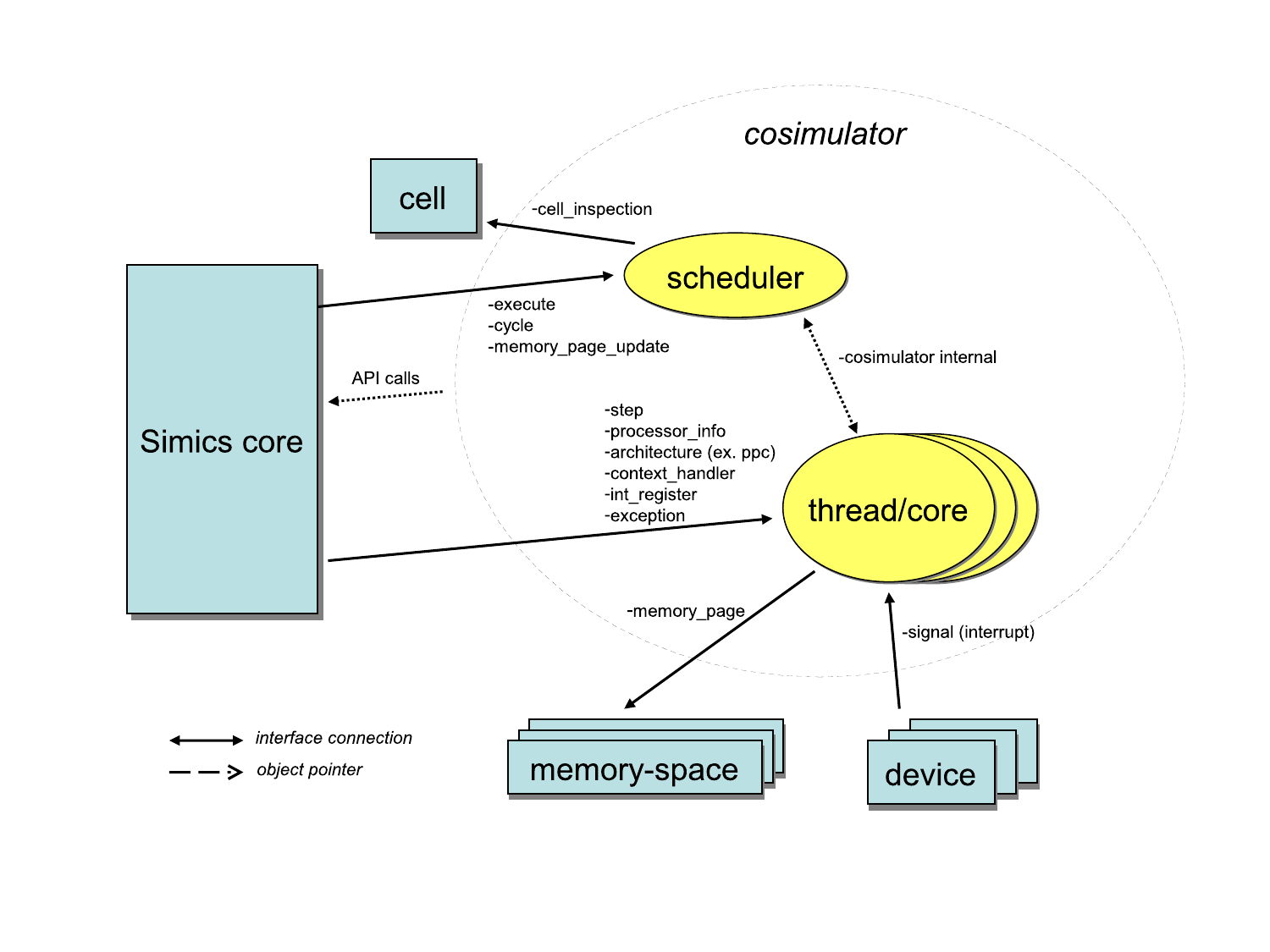
Cycle driven models are typically slow models. The setup only has one clock object which handles timing for all objects in the setup. All objects run in lock step mode where each object run one cycle at a time. Figure 1 shows an example setup of event driven processors. The type of simulation where this setup should be used are for example clock cycle accurate HDL simulator models.
The objects in figure 1 are:
execute interface and the cycle
interface. The clock handles all timing in the system.processor_info_v2,
int_register, and exception
interfaces. These interfaces are used by standard Simics commands for
showing time, events, register contents, instruction disassemble,
etc.
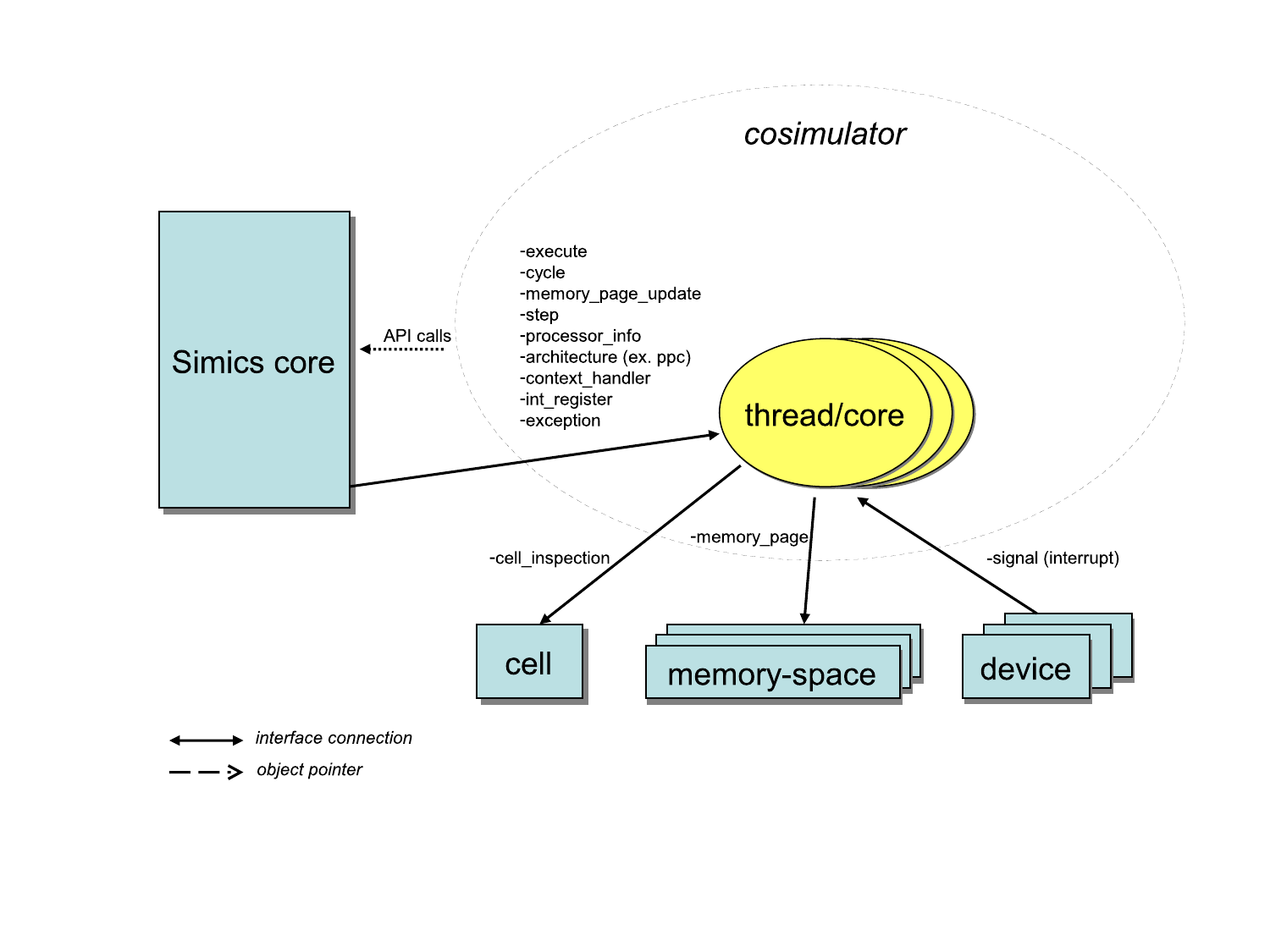
In the setup shown in figure 2, the
processors export one implementation of the time event queue instead
having a Simics object do that. The result is that the processor
model has better control of when new events are added and also that
the processor model triggers the events. The Simics core instructs the
scheduler to run the simulation forward through the
execute interface. All objects in a cell implementing
the execute interface will be kept within a time window
defined by the time_quantum attribute of the cell. Having
a quantum that is significantly larger than a single cycle (as in a
cycle driven model) allows for faster simulation since optimizations
such as binary translation and hypersimulation can then be employed.
The objects in figure 2 are:
execute and
cycle interfaces. Simics core and devices will use this
object for posting events and for driving the simulation. The
scheduler object may correspond to something particular in hardware,
such as a processors with multiple cores.processor_info_v2
interface. These interfaces are used by standard Simics commands for
showing time, events, register contents, instruction disassemble,
etc.The processor model has control of time and can optimize for running long quanta. The Simics core notifies the execute object that it can start to execute and it is up to the implementation to control how everything is scheduled. The threads/cores may be simulated in parallel with multiple threads. Note that care must be taken if typical Simics processor model features such as deterministic execution and reverse execution are to be supported.
An example system with this setup can be found in
[simics]/targets/cosim/queues-in-cosimulator.simics. The
source code for the example can be found in
[simics]/src/extensions/sample-risc.
In the setup shown in figure 3, each
processor implements the scheduling interfaces. This is a special case
of the previous mechanism where each set of processors only include a
single processor. The Simics core instructs the scheduler to run the
simulation forward through the execute interface. All
objects in a cell implementing the execute interface
will be kept within a time window defined by the
time_quantum attribute of the cell. Having a quantum that
is significantly larger than a single cycle (as in a cycle driven
model) allows for faster simulation since optimizations such as binary
translation and hypersimulation can then be employed.
The objects in figure 3 are:
execute and
cycle), and the interfaces used to control and inspect
the individual cores (processor_info_v2,
step, int_register, etc).This model is similar to the previous model with the difference that each thread/core defines its own time domain. This also means that each object will be driven individually by the Simics core. This is the type of model used by all standard processor models in Simics.
This chapter describes the interfaces used for customized simulation scheduling.
The execute interface is implemented by objects that
drive a simulation, which is often processor models. The object
does not have to implement cycle or
step.
An object implementing the execute interface must be
coupled with one object implementing the cycle
interface. It can be the same object that implements the
cycle interface.
The run function is called when the simulator starts or restarts the execution.
By default the Simics scheduler will assume that the object being called in
with the execute interface also implements the corresponding
processor_info and step interfaces.
If this assumption is incorrect, the implementation of the run
function is responsible for maintaining the simulators view of the current
objects implementing the processor_info and
step interfaces. It does that by using the appropriate
functions in the cell_inspection interface. The current
objects must always be correctly set when either the run function
returns, when any API method is called, or when any other object is called
through an interface. Several Simics features, such as CLI commands, device
logging, and hap handling make use of the current objects.
To handle asynchronous events, and thus allow for reasonable interactive
performance, the implementor of execute needs to either make
sure that run returns after not having run for too long, or
preferably regularly call the VT_check_async_events method. In
the Simics library CPU models, VT_check_async_events is called
after servicing events from the cycle or step
interfaces.
The simulator core will call stop when it detects a condition that should interrupt the simulation. The callee should stop as soon as possible when in a stable state, typically when the current executing instruction is finished after getting a request to stop. In some cases the callee might receive multiple stop requests in a rapid sequence. Conditions leading to a stop request include SIM_break_simulation being called from a device or hap-handler, breakpoint triggered, low-memory situations, the user interrupting the simulation with Ctrl-C, and the Simics core halting the object when it is at the end of the allowed time window in temporal decoupled simulation. It is forbidden to do anything in the stop function that can lead to a new stop request, this includes posting events, printing SIM_log-messages, etc. Before returning from the run method, the VT_stop_event_processing function should be called. The requirement to call VT_stop_event_processing is likely to be lifted in future versions of Simics.
The switch_in function is called whenever the execute object is about to gain control of the simulation from some other execute object in the cell. Similarly, switch_out is invoked before control is relinquished. It should be noted that these functions are called in a deterministic manner which is not true for run.
The switch_in and switch_out functions are not called at simulation start (or checkpoint load), in general.
SIM_INTERFACE(execute) {
        void (*run)(conf_object_t *obj);
        void (*stop)(conf_object_t *obj);

        void (*switch_in)(conf_object_t *obj);
        void (*switch_out)(conf_object_t *obj);
};

#define EXECUTE_INTERFACE "execute"
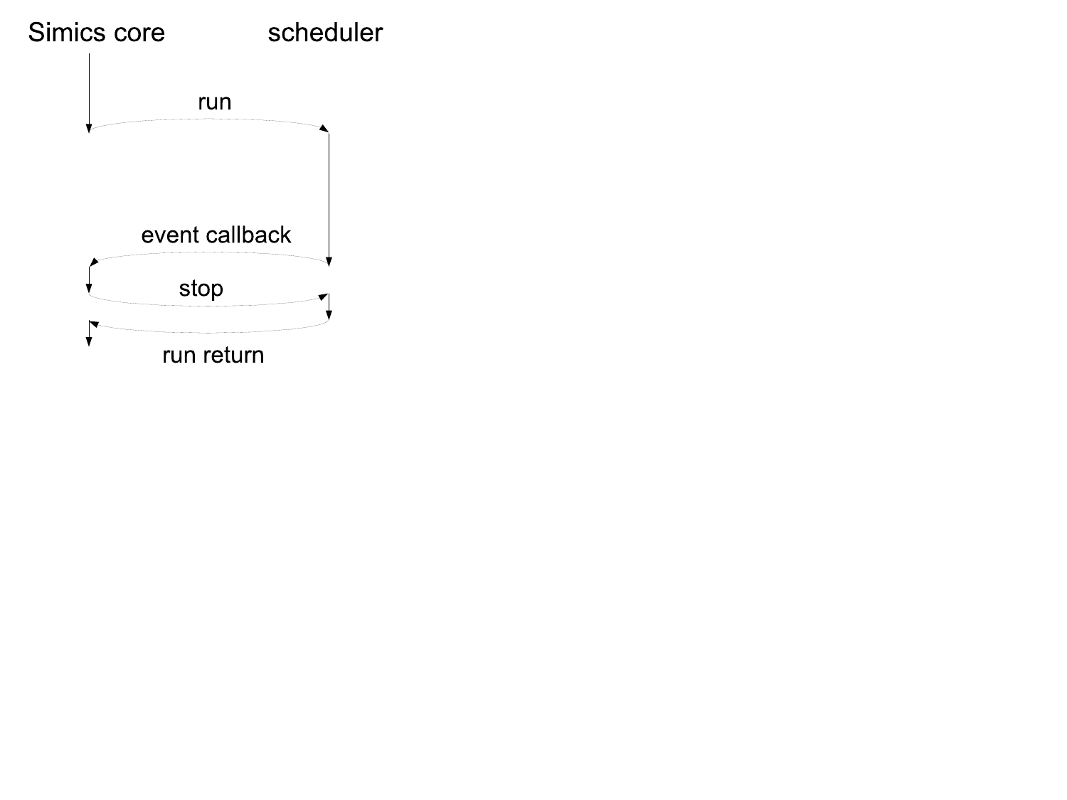
In figure 4 there is an example call-graph of
Simics core and processor scheduler communication. Simics posts events
on the processor's event queues to be triggered, for instance, at
the end of the allowed time window. Simics then calls the
run function in the execute interface and
the processor starts executing instructions. The processor which
implements the event queues will after a while execute an event
callback for the event posted by the Simics core in one of the event
queues. The Simics core handles the event which will trigger a stop
request via the stop function. Note that not all events
will trigger a stop request. Having received stop, the
processor model must stop the simulation as soon as possible and
return to the Simics core. This is typically done as soon as the
currently executing instruction is committed.
The cell_inspection interface is implemented by
objects of the cell class. It is used by objects implementing the
execute interface to update the currently executing
objects when control is transferred outside of the execute object.
The current object implementing processor_info is set with
set_current_processor_obj(). Similarly, the current object
implementing step is set with
set_current_step_obj().
SIM_INTERFACE(cell_inspection) {
        void (*set_current_processor_obj)(conf_object_t *obj,
                                          conf_object_t *cpu_obj);
        void (*set_current_step_obj)(conf_object_t *obj,
                                     conf_object_t *step_obj);
};

#define CELL_INSPECTION_INTERFACE "cell_inspection"
cycle interface is typically implemented by
processors, but can be implemented by other objects as well. Its purpose is
to handle events based on time. The cycle queue has a cycle as the smallest
time unit. The cycle queue also has an associated frequency which makes it
possible to define events based on seconds or picoseconds.
The get_frequency function returns the frequency in Hertz for
the queue. Most objects implementing cycle also
have a notification mechanism for frequency changes through the
simple_dispatcher interface in the cpu_frequency
port. It is recommended that such a notification mechanism is used to get
updates rather than polling with get_frequency.
The current number of cycles executed by the queue is returned by get_cycle_count. Time elapsed since the queue was created is returned by get_time (in seconds) and get_time_in_ps (in picoseconds); this will be equal to the value returned by get_cycle_count divided by the value returned by get_frequency if the frequency has been constant since time zero.
The cycles_delta function returns the highest number of cycles obj can run before it passes the absolute local time when, assuming no frequency change occurs in the meantime. Note that cycles_delta can raise an exception if when was too far ahead in the future. The cycles_delta_from_ps function performs the same function, for an absolute local time expressed in picoseconds.
The post_cycle function will schedule an event that will occur after cycles counted from local current time at queue. The post_time function is similar but takes seconds as argument, while post_time_in_ps takes a number of picoseconds. The arguments cycles, seconds and picoseconds must be nonnegative.
An event previously posted can be removed by calling cancel. The
cancel function takes a function pred as argument
which is called when a matching event is found. The event is only removed if
pred returns 1.
The find_next_cycle, find_next_time and
find_next_time_as_ps functions take the same arguments as
cancel but only return the number of cycles, seconds or
picoseconds before the event occur. The evclass is the event
class, obj is the object posting the event, and
user_data is pointer to data used as a parameter when calling
the callback function defined in the evclass.
If no matching event was found, find_next_cycle and
find_next_time return −1;
find_next_time_as_ps returns ILLEGAL_DURATION.
The events method returns a list of all pending events in expiration order. Each element is a four-element list containing the event object, the event class name, the expiration time counted in cycles as an integer and the event description as given by the event class describe method, or NIL for events whose event class does not define that method.
What happens to already posted events when a frequency change occurs is implementation dependent. Simics processors will scale the cycle queue to keep the time left before triggering events equal across the frequency change. Note that the new times will be rounded to entire cycles during the scaling, so approximations may occur when switching between high and low frequencies.
Objects implementing the cycle interface are usually meant to be scheduled by Simics itself. For this to happen, a number of conditions must be fulfilled:
cycle interface
must be controlled by an object implementing the execute
interface. It can be the same object that implements the
execute interface. The object implementing the
execute interface points to the object implementing the
cycle interface via its queue attribute.cycle interface
must inform Simics about changes in frequency by calling the
VT_clock_frequency_change function. That also applies to the
initial frequency set when the object is created.cycle interface must be
registered with SIM_register_clock, which will also add some
Simics specific attributes to the corresponding class. Beyond those, the
implementor of the cycle can use any checkpoint
representation. The name field in the event class data
structure is unique, and the attribute setter function for checkpoint restore
can use VT_get_event_class to get the event class structure
corresponding to an event class name.
SIM_INTERFACE(cycle) {

        cycles_t (*get_cycle_count)(conf_object_t *queue);
        double (*get_time)(conf_object_t *queue);
        cycles_t (*cycles_delta)(conf_object_t *NOTNULL clock,
                                 double when);

        uint64 (*get_frequency)(conf_object_t *queue);

        void (*post_cycle)(
                conf_object_t *NOTNULL queue,
                event_class_t *NOTNULL evclass,
                conf_object_t *NOTNULL obj,
                cycles_t cycles,
                lang_void *user_data);
        void (*post_time)(
                conf_object_t *NOTNULL queue,
                event_class_t *NOTNULL evclass,
                conf_object_t *NOTNULL obj,
                double seconds,
                lang_void *user_data);

        void (*cancel)(
                conf_object_t *NOTNULL queue,
                event_class_t *NOTNULL evclass,
                conf_object_t *NOTNULL obj,
                int (*pred)(lang_void *data, lang_void *match_data),
                lang_void *match_data);

        cycles_t (*find_next_cycle)(
                conf_object_t *NOTNULL queue,
                event_class_t *NOTNULL evclass,
                conf_object_t *NOTNULL obj,
                int (*pred)(lang_void *data, lang_void *match_data),
                lang_void *match_data);

        double (*find_next_time)(
                conf_object_t *NOTNULL queue,
                event_class_t *NOTNULL evclass,
                conf_object_t *NOTNULL obj,
                int (*pred)(lang_void *data, lang_void *match_data),
                lang_void *match_data);

        attr_value_t (*events)(conf_object_t *NOTNULL obj);

        /* new picoseconds based functions */
        local_time_t (*get_time_in_ps)(conf_object_t *queue);
        cycles_t (*cycles_delta_from_ps)(conf_object_t *NOTNULL clock,
                                         local_time_t when);
        void (*post_time_in_ps)(
                conf_object_t *NOTNULL queue,
                event_class_t *NOTNULL evclass,
                conf_object_t *NOTNULL obj,
                duration_t picoseconds,
                lang_void *user_data);

        duration_t (*find_next_time_in_ps)(
                conf_object_t *NOTNULL queue,
                event_class_t *NOTNULL evclass,
                conf_object_t *NOTNULL obj,
                int (*pred)(lang_void *data, lang_void *match_data),
                lang_void *match_data);
};

#define CYCLE_INTERFACE "cycle"
Experimental, may change without notice.
SIM_INTERFACE(co_execute) {
        void (*start_thread)(conf_object_t *NOTNULL obj,
                             void (*entry)(lang_void *arg), lang_void *arg);
        void (*yield)(conf_object_t *NOTNULL obj);
};
#define CO_EXECUTE_INTERFACE "co_execute"
Experimental, may change without notice.
SIM_INTERFACE(synchronous_mode) {
        int (*enter)(conf_object_t *NOTNULL obj);
        int (*leave)(conf_object_t *NOTNULL obj);
};
#define SYNCHRONOUS_MODE_INTERFACE "synchronous_mode"
The processor API includes support for caching pointers to simulated memory so that the model can perform accesses directly instead of having to use the API for every individual access.
This chapter describes the interfaces and API calls used to setup and handle direct access to memory.
The direct_memory_lookup interface is implemented by Simics
memory-spaces. The interface is used by simulator objects that want to do
fast accesses to memory and/or want to build up a cached representation of
memory. These objects are referred to as memory users, e.g., processors.
Fast accesses are done via host pointers to simulated memory. The
direct_memory_lookup interface is used in conjunction with
the direct_memory interface which is implemented by objects
that own the actual data storage, e.g., RAM/ROM objects. These objects are
called direct-memory objects.
To access data, a memory-user object first calls the lookup method on the memory space obj. The requester is the memory-user doing the lookup. The lookup method traces the range specified by addr and size through memory spaces and translators until a direct-memory object is reached. The direct-memory object is returned in the target field and the offset into this object corresponding to addr is returned in the offs field.
The call to lookup fails if the specified range does not map continuously to a direct-memory object. A lookup failure is indicated by returning NULL in the target field.
The access argument is a bit field of at least one
access_t value specifying what kind of accesses the memory user
is interested in. All specified access types must reach the same
direct-memory object and range for the lookup to succeed. If the memory
space, for example, redirects reads and writes to different memory ranges or
direct-memory objects, a lookup would fail if access
specified both read and write. Note that the actual access permissions
needed to access the real data must be requested from
the direct-memory object using the request method of
the direct_memory interface. The access
argument is only used to locate the direct-memory object.
The return field access contains at least the access bits requested used in the lookup request, but may as an optimization contain a superset, indicating that the lookup result is valid for this superset. However, there is no guarantee that this optimization takes place.
Once a direct-memory object has been found, the direct_memory
interface can be used to obtain a direct pointer to the contents
of the direct-memory object.
The tracers and breakpoints fields in the
return value contain information about installed tracers and breakpoints
that intersect the range. Examples of tracers are timing models
and snoop objects. In order to trigger breakpoints and invoke any tracers,
the memory user should perform memory operations using the
memory_space interface. Only breakpoints and tracers that
overlap (binary and) with the provided access argument need to be
considered.
typedef struct {
        conf_object_t     *target;
        uint64             offs;

        access_t           breakpoints;      // conflicting breakpoints
        access_t           tracers;          // conflicting tracers
        access_t           access;           // handle valid for access
} direct_memory_lookup_t;
SIM_INTERFACE(direct_memory_lookup) {
        direct_memory_lookup_t (*lookup)(conf_object_t *NOTNULL obj,
                                         conf_object_t *requester,
                                         physical_address_t addr,
                                         unsigned size,
                                         access_t access);
};

#define DIRECT_MEMORY_LOOKUP_INTERFACE "direct_memory_lookup"
The direct_memory_lookup and direct_memory
interfaces replace the memory_page interface of Simics 4.8.
The direct_memory interface is implemented by objects that
model memory, such as RAM and ROM objects. These are called direct-memory
objects. A user of the interface is called a memory user and is
typically a processor that wants to do fast accesses to memory. The
direct-memory object corresponding to a particular physical address
can be obtained using the lookup method of the
direct_memory_lookup interface.
See the documentation for the
direct_memory_lookup interface for more information.
A memory user using the direct_memory interface
must implement the direct_memory_update interface.
The get_handle method is used by a memory user to create or retrieve a handle to the memory region starting at offset offs with size size. The handle is typically used later on to request access permissions and to retrieve a direct pointer to the region. The handle returned by get_handle is private to the memory user specified in the requester parameter.
If get_handle is invoked multiple times for the same range, and with identical requester and subsystem arguments, then the same handle will be returned each time, assuming the original handle is still valid. Note that the original handle is only returned if the range matches exactly. A single memory user can obtain multiple distinct handles for the same memory range by using different values for the subsystem parameter.
For RAM and ROM, offs and size must specify a region which does not intersect a naturally aligned 8192 byte boundary, or the request will fail with a NULL return value. Other direct-memory objects might have different requirements.
The request method is used to request a host pointer to simulated memory. This pointer can be used to carry out fast memory operations without having to involve the Simics API. The handle argument is the handle obtained using get_handle.
Both the permission argument and the inhibit argument
are access_t type bit fields. The permission
argument is used to specify what kind of memory operations the memory user
will perform. For example, if a memory user wants to read memory, the
permission argument must include the Sim_Access_Read value. The
inhibit argument specifies what other memory users are not
allowed to do. For example, if inhibit is set to Sim_Access_Write
other memory users are not allowed to write to the memory range. This
protection mechanism can be used to create caches of simulated memory,
request exclusive permissions to a memory range in order to carry out atomic
operations, and similar. When a memory user is requesting permission to a
memory range that another memory user has protected with conflicting inhibit
bits, the direct-memory object will inform the other memory user of
the lost permissions and protection through the
direct_memory_update interface. A user can lose both the
permission and protection for a memory range in this way. When this happens,
a memory user may re-request permissions and inhibit protection.
Note: if a memory user has multiple handles which overlaps, then each handle is considered to be a distinct memory user. For example, if a memory user holds two handles, and requests write inhibit on one of them, then write permission will be revoked from the second handle (if such permission had been granted).
The request method returns a direct_memory_t value
with information about the retrieved permissions and inhibit bits. These
bits can be a super set of the bits that actually were requested. The
returned data pointer can be used to access the memory range. Accesses are
valid from the data pointer and up to the end of the range, i.e., addresses
up to data pointer + size - 1, where size is the size valid for
the handle. A call to request always succeeds and the
corresponding memory range is valid until the permissions or the handle are
revoked by the direct_memory_update interface. Note that the
data pointer may change each time request is called (with the
same handle) since Simics may move simulated memory. If the pointer
changes, then the old pointer must not be used.
With set_user_data, a memory user can associate a user-defined pointer with a specific handle. The pointer can be retrieved using the get_user_data method, which takes a handle as an argument.
A memory user can use the release function to notify the direct-memory object when it is no longer interested in the memory region corresponding to handle. The handle is invalid and must not be used for anything after being released.
The ack method is used by a memory user to inform the
direct-memory object that it has given up the corresponding permission and
inhibit rights for a memory range when called by a method in the
direct_memory_update interface.
Permissions can be revoked from all memory users by invoking the
revoke method. The permission parameter
specifies the permissions which will be revoked from all memory users.
Similarly, inhibit specifies the inhibit privileges which
will be revoked. For instance, calling revoke with
permission
set to Sim_Access_Write will ensure that nobody has
write permissions to the direct-memory object.
typedef granted_mem_t *direct_memory_handle_t;
typedef struct {
#ifndef PYWRAP
        uint8                 *data;
#endif
        access_t               permission;
        access_t               inhibit;
} direct_memory_t;
typedef uint64 direct_memory_ack_id_t;
SIM_INTERFACE(direct_memory) {
        direct_memory_handle_t (*get_handle)(conf_object_t *NOTNULL obj,
                                             conf_object_t *NOTNULL requester,
                                             uint64 subsystem,
                                             uint64 offs,
                                             unsigned size);
        direct_memory_t (*request)(conf_object_t *NOTNULL obj,
                                   direct_memory_handle_t handle,
                                   access_t permission,
                                   access_t inhibit);
        void (*revoke)(conf_object_t *NOTNULL obj,
                       access_t access,
                       access_t permission,
                       access_t inhibit);
#ifndef PYWRAP
        void *(*get_user_data)(conf_object_t *NOTNULL obj,
                                    direct_memory_handle_t handle);
        void (*set_user_data)(conf_object_t *NOTNULL obj,
                              direct_memory_handle_t handle,
                              void *user_data);
#endif
        void (*release)(conf_object_t *NOTNULL obj,
                        direct_memory_handle_t handle);
        void (*ack)(conf_object_t *NOTNULL obj,
                    direct_memory_ack_id_t id);
};

#define DIRECT_MEMORY_INTERFACE "direct_memory"
The direct_memory_flush interface is implemented by objects
that model memory, such as RAM and ROM objects, and is used for flushing
granted rights and for managing access rights.
The revoke method revokes granted access, permissions and inhibit rights from memory-user regions intersecting [base, base + size).
The set_access_bits method grants access rights access for the region [base, base + size) to the memory user requester. If requester is NULL, then access rights are granted to all memory users. If the set succeeds, true is returned, otherwise false.
SIM_INTERFACE(direct_memory_flush) {
        void (*revoke)(conf_object_t *NOTNULL obj,
                       uint64 base, uint64 size,
                       access_t access, access_t perm, access_t inhibit);
        bool (*set_access_bits)(conf_object_t *NOTNULL obj,
                                conf_object_t *requester,
                                uint64 base, uint64 size,
                                access_t access);
};
#define DIRECT_MEMORY_FLUSH_INTERFACE "direct_memory_flush"
The direct_memory_update interface must be implemented by
memory-user objects that use the direct_memory interface.
The direct_memory_update interface replaces the
memory_page_update interface from Simics 4.8.
Accesses to memory are controlled by a handle that the memory-user object
requests by calling the get_handle method of the
direct_memory interface. The object implementing the
direct_memory interface through which the handle was
established is passed to the functions in
direct_memory_update as target.
If the release method is called, the corresponding
handle and all the permissions and inhibit protections are
recalled. The memory-user object must stop using the handle and
associated data pointers and then call the acknowledge method
ack in the direct_memory interface from
which the handle was granted.
A call to the update_permission method revokes earlier requested
rights for a handle. The lost_access argument recalls rights to
use the handle for the given access bits. This means that the handle needs
to be re-fetched (by a call to the lookup method of the
direct_memory_lookup interface followed by a call to the
get_handle method of the direct_memory interface)
before the handle can be used again for the particular access. This typically
happens if a new breakpoint is inserted or a remap of the memory system is
done. In case of a remap it is possible that the same handle will never be
returned again which means that any user data associated with the handle
should be reclaimed.
The lost_permission and the lost_inhibit arguments describe which permission rights and inhibit protection that are revoked. However, in contrast to the lost_access, the handle is still valid and can be used to re-request permission rights and inhibit protection.
A call to the conflicting_access method informs a memory-user object that a conflicting memory operation will be performed. Hence, if the memory-user object have some protected representation of memory (such as decoded instructions in an internal cache), that representation of memory has to be flushed (or written back to memory in case of dirty data). Note however that the memory-user object does not lose any permission rights or any inhibit protection.
There is no mechanism for locking simulated memory in host memory.
All methods in this interface receive a direct_memory_ack_id_t
value as an argument. The ack method of the
direct_memory interface must be called with this
id as an argument when the corresponding operation has been
carried out. The ack method may be called after the
direct_memory_update interface function has returned, which
allows for queueing of update requests. This may be valuable if multiple
simulator threads are used.
An exception to the allowed queueing of update requests is for update
requests that are received while calling request in the
direct_memory interface. Such requests must be handled
immediately with ack being called before the return of the
direct_memory_update interface function. This requirement
avoids a dead-lock that would otherwise happen if request would
wait for ack before returning, but ack is
queued to be handled at some time after request has returned.
SIM_INTERFACE(direct_memory_update) {
        void (*release)(conf_object_t *NOTNULL obj,
                        conf_object_t *NOTNULL target,
                        direct_memory_handle_t handle,
                        direct_memory_ack_id_t id);
        void (*update_permission)(conf_object_t *NOTNULL obj,
                                  conf_object_t *NOTNULL target,
                                  direct_memory_handle_t handle,
                                  access_t lost_access,
                                  access_t lost_permission,
                                  access_t lost_inhibit,
                                  direct_memory_ack_id_t id);
        void (*conflicting_access)(conf_object_t *NOTNULL obj,
                                   conf_object_t *NOTNULL target,
                                   direct_memory_handle_t handle,
                                   access_t conflicting_permission,
                                   direct_memory_ack_id_t id);
};

#define DIRECT_MEMORY_UPDATE_INTERFACE "direct_memory_update"
The processor state can be controlled and inspected using commands or GUI controls. This chapter describe the interfaces, haps, and breakpoint functionality required for supporting this.
Several generic Simics commands automatically works by just implementing standard interfaces. How the interfaces map onto objects depend on how the model is designed, for example the type of models described in Chapter 2.
This section lists the interfaces that can be implemented by the processor model to enable certain Simics features. They are not required, but implementing them will allow user defined processor models to support the same generic feature set as Simics standard processor models. If you intend to plug your model into an existing Simics-provided platform, then many of these interfaces are actually required for such a platform to function.
The processor_info_v2 interface is implemented by
processors models. The interface has processor generic functions
that are architecture independent.
The disassemble function returns the disassemble string for an
instruction at address with opcode according to
instruction_data. The instruction_data is an
attr_value_t value of data type with the bytes of the
opcode. The bytes are in the same order as they are stored in memory. For
VLIW architectures, sub_operation is used to select which
sub-operation to disassemble. The sub-operations start at zero, and a
request for the entire unit including all sub-operations is encoded with
sub-operation -1. A request for a sub-operation that is not present (for
example when sub-operation is neither 0 nor -1 for non-VLIW
architectures) results in the integer part of the return tuple being set to
zero. If successful, the function should return a tuple with the size of the
instruction in bytes and the disassembly string. The disassembly string
should be allocated with MM_MALLOC or similar and is to be freed by the
caller. If more bytes are needed, then the function should indicate that by
returning a negative number in the tuple where the absolute value of the
number is the required number of bytes. The string should be NULL if more
bytes are needed. The implementor of processor_info_v2 is
allowed to request one additional byte at a time until enough bytes are
passed to determine what the instruction is. Illegal instructions should
still result in a valid returned tuple, where the integer part will be used
by the disassemble command to skip that many bytes before disassembling the
next instruction. The address can be used to display absolute
destinations of program counter relative branches.
The set_program_counter function sets the program counter in the processor. The get_program_counter function returns the current program counter.
The logical_to_physical function translates a logical
address to a physical address of the type defined by
access_type. The function returns a physical_block_t
struct with valid bit and the address. The
address is valid when the valid bit is not 0. The
logical_to_physical function also returns
block_start and block_end. The start and end
of a block has the same logical to physical transformation as the translated
address. The range is inclusive, so block_end should be the
address of the last byte of the block.
This information can be used to figure out how often the
logical_to_physical function needs to be called. An implementation would
typically return the page start and end here, but it is free to return any
power of 2 sized block as long as it includes the translated address.
The current operating mode of the processor is returned with get_processor_mode.
The processor can be enabled or disabled with the
enable_processor or disable_processor
functions. The functions should return 0 if the processor
changed from enabled to disabled or from disabled to enabled, and
1 if the processor did not change state. The current state
is returned by the get_enabled function. Enabled or
disabled here refers to the state that the user of the model has
put the processor into. In particular, it is independent of the
power mode of the processor. A processor that has powered down does
not count as disabled in this sense, nor does the
enable_processor wake up a processor that is in
a power-saving sleep state.
The endianness of the processor is returned by the get_endian function.
The physical memory object is returned by the
get_physical_memory function. The object returned by
get_physical_memory is used to set breakpoints by the
global break command, and to read and write physical
memory through set, get,
load-binary, load-file, and the default
implementation of disassemble. The object returned
implements the memory_space and
breakpoint interfaces. The
memory_space interface for the returned object is
only be used in inquiry mode corresponding to actions by the
simulator itself rather than by the simulated software. An
implementation may return NULL from this method, which will lead to
the command listed above not being supported when such a processor
is selected.
The get_logical_address_width function returns the number of logical/virtual address bits and the get_physical_address_width function returns the number of physical address bits.
The processor architecture is returned by calling the
architecture function. The architecture should be one of
arm, mips32,
mips64, ppc32, ppc64, sparc-v8,
sparc-v9, x86, x86-64, or something else
if none of the listed is a good match.
All functions in the interface are optional. Each function can be set to NULL if it is not supported.
SIM_INTERFACE(processor_info_v2) {
        tuple_int_string_t (*disassemble)(conf_object_t *obj,
                                          generic_address_t address,
                                          attr_value_t instruction_data,
                                          int sub_operation);
        void (*set_program_counter)(conf_object_t *obj,
                                    logical_address_t pc);
        logical_address_t (*get_program_counter)(conf_object_t *obj);
        physical_block_t (*logical_to_physical)(conf_object_t *obj,
                                                logical_address_t address,
                                                access_t access_type);
        processor_mode_t (*get_processor_mode)(conf_object_t *obj);
        int (*enable_processor)(conf_object_t *obj);
        int (*disable_processor)(conf_object_t *obj);
        int (*get_enabled)(conf_object_t *obj);

        cpu_endian_t (*get_endian)(conf_object_t *obj);
        conf_object_t *(*get_physical_memory)(conf_object_t *obj);

        int (*get_logical_address_width)(conf_object_t *obj);
        int (*get_physical_address_width)(conf_object_t *obj);

        const char *(*architecture)(conf_object_t *obj);
};

#define PROCESSOR_INFO_V2_INTERFACE "processor_info_v2"
Note that the original version of this interface
(processor_info) must also be implemented. The only
difference between the two interfaces is that the original version lacks the
get_processor_mode function.
Some commands and features in the CLI use the
processor_cli interface. Those commands will have
limited functionality if the interface is not fully implemented.
The first argument to each function is the object to act on. This object
should implement both the processor_info interface and the
processor_cli interface.
The get_disassembly function is used for the disassemble command as well as to disassemble the next instruction to be executed, when control is returned to the CLI prompt. For most architectures, get_disassembly can be set to NULL, in which case the command will use other interfaces to provide a generic disassembly. The get_disassembly function should return a tuple with the length of the instruction in bytes and the disassembly string. The addr_prefix parameter selects the address type of the address parameter, whether it is a physical address ("p"), a linear address ("l") or a virtual address ("v"), just as returned from get_address_prefix. The address parameter is the program counter for the instruction to disassemble. If print_cpu is non-zero, then the name of the processor should be included first in the disassembly line. If mnemonic is not NULL, then it should be output instead of the instruction disassemble. The mnemonic is used to print exception or interrupt information as returned by the get_pending_exception_string function.
get_pregs returns the string to output in the CLI for the print-processor-registers command. The all parameter is a boolean corresponding to the -all switch to the print-processor-registers command.
The diff_regs function is used by the stepi
command when the -r flag is used. The
diff_regs function returns a list of register names,
where each register in that list will be read through the
int_register interface before and after an
instruction.
When returning to the CLI prompt, information about the next
instruction or step to execute is printed. Normally, that is the
disassemble of the instruction at the current program counter. The
get_pending_exception_string function is called before
the disassembly to find out if the next step will not be an
instruction, but rather a taken exception or interrupt. The
function should inspect the given cpu (an object
implementing processor_info and
processor_cli) and return NULL if the next step will
be the execution of the instruction at the current program
counter. If the next step will instead be the handling of an
exception or interrupt, then a string saying that should be
returned.
The get_address_prefix function returns a string with the default address prefix for memory related commands. Simics defines the generic prefixes "v" for virtual addresses, "l" for linear addresses, and "p" for physical addresses. The default if get_address_prefix is NULL is "v" for virtual addresses.
translate_to_physical translates an address to a
physical address. If translate_to_physical is NULL, then
the only allowed address prefixes are "v" (virtual) and "p"
(physical), and the logical_to_physical function in the
processor_info interface will be used to translate
virtual addresses.
SIM_INTERFACE(processor_cli) {
	tuple_int_string_t (*get_disassembly)(conf_object_t *obj,
                                              const char *addr_prefix,
                                              generic_address_t address,
                                              bool print_cpu,
                                              const char *mnemonic);
	char *(*get_pregs)(conf_object_t *cpu,
                           bool all);
	attr_value_t (*get_diff_regs)(conf_object_t *obj);
	char *(*get_pending_exception_string)(conf_object_t *obj);
	char *(*get_address_prefix)(conf_object_t *obj);
	physical_block_t (*translate_to_physical)(conf_object_t *obj,
                                                  const char *prefix,
                                                  generic_address_t address);
};

#define PROCESSOR_CLI_INTERFACE "processor_cli"
The processor_gui interface is implemented by
processors that support displays in the Simics native GUI. It is
only registered to indicate support for the displays, and does not
contain any actual functionality.
SIM_INTERFACE(processor_gui) {
        void (*dummy)(conf_object_t *obj);
};

#define PROCESSOR_GUI_INTERFACE "processor_gui"
The step interface is typically implemented by
processors, but can be implemented by other objects as well. Its
purpose is to handle step events using a queue.
The current number of steps for the queue is returned when calling get_step_count.
The post_step function will schedule an event that will
occur after steps (which must be nonnegative)
counted from local current step at
queue. An event previously posted can be removed by
calling cancel_step. The cancel_step function takes a
function pred as argument which is called when a matching
event is found. The event is only removed if pred returns
1. The find_next_step takes the same arguments
as cancel_step but only returns the number of cycles before
the event will occur. The evclass is the event class,
obj is the object posting the event, and
user_data is pointer to data used as a parameter when
calling the callback function defined in the evclass.
If no matching event was found, find_next_step returns
−1.
The events method returns a list of all pending events in expiration order. Each element is a four-element list containing the event object, the event class name, the expiration time counted in steps as an integer and the event description as given by the event class describe method, or nil for events whose event class do not define that method.
The advance function will increment the number of steps for the queue, decrementing the number of steps to the first event to the value defined by steps. The number of steps remaining to the next event is returned. It is an error to advance beyond the next pending event, so the return value is never negative.
The implementor of the step interface can use any
checkpoint representation. The name field in the
event class data structure is unique, and the attribute setter
function for checkpoint restore can use
VT_get_event_class to get the event class structure
corresponding to an event class name.
SIM_INTERFACE(step) {
        pc_step_t (*get_step_count)(conf_object_t *NOTNULL queue);
        void (*post_step)(
                conf_object_t *NOTNULL queue,
                event_class_t *NOTNULL evclass,
                conf_object_t *NOTNULL obj,
                pc_step_t steps,
                lang_void *user_data);
        void (*cancel_step)(
                conf_object_t *NOTNULL queue,
                event_class_t *NOTNULL evclass,
                conf_object_t *NOTNULL obj,
                int (*pred)(lang_void *data, lang_void *match_data),
                lang_void *match_data);
        pc_step_t (*find_next_step)(
                conf_object_t *NOTNULL queue,
                event_class_t *NOTNULL evclass,
                conf_object_t *NOTNULL obj,
                int (*pred)(lang_void *data, lang_void *match_data),
                lang_void *match_data);

        attr_value_t (*events)(conf_object_t *NOTNULL obj);

        pc_step_t (*advance)(conf_object_t *queue, pc_step_t steps);
};

#define STEP_INTERFACE "step"
The step_cycle_ratio interface is implemented by
processors that support a changeable ratio between steps and
cycles. The set-step-rate command uses this interface to
set the ratio between steps and cycles.
The set_ratio sets the ratio between steps and cycles. Note that the introduction of stall cycles can skew the ratio. The get_ratio simply returns the current ratio.
The cycles and step arguments must be in the range [1..128] and cycles must be a power of two. Implementers of this interface may choose to ignore other values of cycles and step and may log an error.
typedef struct {
        uint32 steps;
        uint32 cycles;
} step_cycle_ratio_t;

SIM_INTERFACE(step_cycle_ratio) {
        step_cycle_ratio_t (*get_ratio)(conf_object_t *obj);
        void (*set_ratio)(conf_object_t *obj, uint32 steps, uint32 cycles);
};

#define STEP_CYCLE_RATIO_INTERFACE "step_cycle_ratio"
The stall interface can be implemented by objects that also
implement the cycle and step interfaces. The
stall interface controls the addition of extra cycles between
steps.
The get_stall_cycles function returns the remaining number of stall cycles. The object will advance that number of cycles before starting with the next step.
The set_stall_cycles function is used to change the number of stall cycles before the next step. It is legal to first call this function with a large value for cycles and then at a later point reduce the cycle count is resume execution earlier than indicated by the first call.
The get_total_stall_cycles returns the total accumulated number of stall cycles.
SIM_INTERFACE(stall) {
        cycles_t (*get_stall_cycles)(conf_object_t *obj);
        void (*set_stall_cycles)(conf_object_t *obj, cycles_t cycles);
        cycles_t (*get_total_stall_cycles)(conf_object_t *obj);
};
#define STALL_INTERFACE "stall"
The int_register
interface is used for access to registers in a processor. It
can be used to access any kind of integer register, not only the
"normal" registers. This includes all kinds of control registers,
hidden registers and anything else that might be useful to access as
a register. The only limitation is that the register value should
be representable as a 64-bit unsigned integer.
This interface can be implemented by other classes than processors, but it is likely to be found mostly in processors.
Registers are identified by a number, and there are two functions to translate from register names to register numbers and back. The translation need not be one-to-one, which means that one register can have several names. A register name can, however, only translate to a single register number.
Often, registers are grouped in register banks, where registers in the bank are numbered from 0 up. Registers in a bank should have consecutive numbers (unless their numbering is very sparse). This allows a user to deduce register numbers by calling get_number for the first register only. The first register numbers should be used for the general-purpose integer registers, if possible (so that integer register rN has number N).
Using this interface to read or write registers does not cause any side effects, such as triggering interrupts or signalling haps.
get_number translates a register name to its number. Returns -1 if the register does not exist.
get_name translates a register number to its canonical name.
read reads a register value.
write writes a new register value.
all_registers returns a list of all register numbers that can be used for this object.
register_info returns information about a single register. The information return depends on the info parameter.
Core_Control_Register_Write and
Core_Control_Register_Read are triggered when this
register is written or read.typedef enum {
Sim_RegInfo_Catchable
} ireg_info_t;
SIM_INTERFACE(int_register) {
        int (*get_number)(conf_object_t *NOTNULL obj,
                          const char *NOTNULL name);
        const char *(*get_name)(conf_object_t *NOTNULL obj, int reg);
        uint64 (*read)(conf_object_t *NOTNULL obj, int reg);
        void (*write)(conf_object_t *NOTNULL obj, int reg, uint64 val);
        attr_value_t (*all_registers)(conf_object_t *NOTNULL obj);
        int (*register_info)(conf_object_t *NOTNULL obj, int reg,
                             ireg_info_t info);
};

#define INT_REGISTER_INTERFACE "int_register"
SIM_INTERFACE(decoder) {
        void (*register_decoder)(conf_object_t *obj,
                                 decoder_t *NOTNULL decoder);
        void (*unregister_decoder)(conf_object_t *obj,
                                   decoder_t *NOTNULL decoder);
};
The decoder interface is implemented by processors
that allows connecting user decoders. This allows a user to
implement the semantics of instructions that are not available in
the standard Simics model or change the semantics of instructions
implemented by Simics. This interface replaces
SIM_register_arch_decoder and
SIM_unregister_arch_decoder functions.
The register_decoder function adds a decoder and unregister_decoder removes a decoder.
The decoder is installed/removed for every object of the same class as the obj argument which must be the same object from which the interface was fetched.
When Simics decodes an instruction, it will first see if any instruction decoders are registered for the current CPU class. For any decoders it finds, Simics will let it try to decode the instruction. The decoders are called in order, starting with the last registered decoder, and if one decoder accepts the instruction, the rest of the decoders will not be called.
The decoder is specified by the decoder_t data structure that the
user supplies:
typedef struct {
        void *user_data;
        int (*NOTNULL decode)(uint8 *code,
                              int valid_bytes,
                              conf_object_t *cpu,
                              instruction_info_t *ii,
                              void *user_data);
        tuple_int_string_t (*NOTNULL disassemble)(uint8 *code,
                                                  int valid_bytes,
                                                  conf_object_t *cpu,
                                                  void *user_data);
        int (*NOTNULL flush)(instruction_info_t *ii,
                             void *user_data);
} decoder_t;
The decode function is called to decode an instruction pointed to by code. The first byte corresponds to the lowest address of the instruction in the simulated memory. valid_bytes tells how many bytes can be read. The CPU is given in the cpu parameter. When the decoder has successfully decoded an instruction, it should set the ii_ServiceRoutine, the ii_Arg, and the ii_Type members of the ii structure (see below), and returns the number of bytes used in the decoding. If it does not apply to the given instruction, it should return zero. If the decoder needs more data than valid_bytes it should return a negative number corresponding to the total number of bytes it will need to continue the decoding. The underlying architecture limits the number of bytes that can be requested, e.g. no more than 4 bytes can be requested on most RISC architectures. Simics will call the decoder again when more bytes are available. This process is repeated until the decoder accepts or rejects the instruction. A decoder should never request more data than it needs. For example, if an instructions can be rejected by looking at the first byte, the decoder should never ask for more bytes.
The instruction_info_t is defined as follows:
typedef struct instruction_info {
        service_routine_t  ii_ServiceRoutine;
        uint64             ii_Arg;
        unsigned int       ii_Type;
        lang_void         *ii_UserData;
        logical_address_t  ii_LogicalAddress;
        physical_address_t ii_PhysicalAddress;
} instruction_info_t;
ii_ServiceRoutine is a pointer to a function that will be called by Simics every time the instruction is executed. It has the following prototype:
typedef exception_type_t (*service_routine_t)(conf_object_t *cpu,
                                              uint64 arg,
                                              lang_void *user_data);
The service routine function should return an exception when it is
finished to signal its status. If no exception occurs
Sim_PE_No_Exception should be returned.
See exception_type_t in
src/include/simics/base/memory.h for the different
exceptions available.
A special return value, Sim_PE_Default_Semantics, can be
returned; this signals Simics to run the default semantics for the
instruction. This is useful if the semantics of an instruction
should be changed but the user routine does not want to handle it all
the time.
Note that in a shared memory multiprocessor, the CPU used in decoding may differ from the CPU that executes the instruction, since the decoded instructions may be cached.
ii_Arg is the argument arg that will be passed on to the service routine function. Op code bit-fields for the instruction such as register numbers or intermediate values can be stored here. The ii_UserData field can also be used to pass information to the service routine if more data is needed.
ii_Type is either UD_IT_SEQUENTIAL or
UD_IT_CONTROL_FLOW. A sequential type means that the
instruction does not perform any branches and the update of the
program counter(s) is handled by Simics. In a control flow
instruction on the other hand it is up to the user to set the
program counter(s).
ii_LogicalAddress and ii_PhysicalAddress holds the logical and physical addresses of the instruction to be decoded.
The disassemble function is called to disassemble an
instruction. It uses the same code,
valid_bytes, and cpu parameters as
the decode function. If the disassembly is valid, then
the string part of the returned tuple_int_string_t struct
should be a MALLOCed string with the disassembly and the integer
part should be its length in bytes. The caller is responsible for
freeing the disassembly string. The string member should be NULL
and the integer part should be zero if the disassembly is not
valid. If the disassemble function needs more data than
valid_bytes it should return a negative number in
the integer part in the same way as the decode function,
and set the string part to NULL.
The flush function is called to free any memory
allocated when decoding an instruction and any user data associated
with the instruction. It should return zero if it does not
recognize the instruction, and non-zero if it has accepted it.
Usually, the way to recognize if a decoded instruction is the right
one to flush is to compare ii->ii_ServiceRoutine with the
function that was set in the decode function. Note
that the cpu parameter is the processor that caused
the flush. It is more or less an arbitrary processor and should be
ignored.
In addition to the function pointers, the
decoder_t structure contains a
user_data pointer that is passed to all the
functions. This can be used for passing any data to the decoder
functions.
The exception interface is used together with the
Core_Exception hap to enable inspection abilities for triggered
exceptions.
The exception interface is used to translate
exception numbers, as received by the Core_Exception hap, to names,
and vice versa.
The get_number function returns the number associated with an exception name, or -1 if the no exception with the given name exist. The get_name returns the name associated with an exception number. The get_source function is only used on X86 targets and returns the source for an exception, as an exception number can be raised from different sources. The all_exceptions function returns a list of all exceptions numbers.
The exception numbers are architecturally defined, while their names are defined by the model.
SIM_INTERFACE(exception) {
        int (*get_number)(conf_object_t *NOTNULL obj,
                          const char *NOTNULL name);
        const char *(*get_name)(conf_object_t *NOTNULL obj, int exc);
        int (*get_source)(conf_object_t *NOTNULL obj, int exc);
        attr_value_t (*all_exceptions)(conf_object_t *NOTNULL obj);
};

#define EXCEPTION_INTERFACE "exception"
SIM_INTERFACE(context_handler) {
        conf_object_t *(*get_current_context)(conf_object_t *obj);
        int (*set_current_context)(conf_object_t *obj, conf_object_t *ctx);
};

#define CONTEXT_HANDLER_INTERFACE "context_handler"
The exec_trace interface is implemented by processor models
that support tracing. A trace listener registers itself with the
register_tracer call. The tracer callback will be
called by the processor model
when each instruction is just about to be executed, passing the
tracer_data as passed to the register_tracer function
in addition to information about the instruction that is executed.
Invoke unregister_tracer with the same two pointers to deregister
the listener.
typedef void (*instruction_trace_callback_t)(lang_void *tracer_data,
                                             conf_object_t *cpu,
                                             linear_address_t la,
                                             logical_address_t va,
                                             physical_address_t pa,
                                             byte_string_t opcode);
The pa parameter to the callback will always be valid, but some CPU architectures may not support la or va. The la argument is typically only valid for x86 CPUs. Lastly, the opcode of the instruction is passed in opcode. The opcode is passed without endian conversion, meaning that byte X in opcode corresponds to the byte at pa + X.
SIM_INTERFACE(exec_trace) {
        void (*register_tracer)(conf_object_t *NOTNULL cpu_obj,
                                instruction_trace_callback_t tracer,
                                lang_void *tracer_data);
        void (*unregister_tracer)(conf_object_t *NOTNULL cpu_obj,
                                  instruction_trace_callback_t tracer,
                                  lang_void *tracer_data);
};

#define EXEC_TRACE_INTERFACE "exec_trace"
The opcode_info interface is implemented by
processors that need to communicate information about the encoding
of instructions to the GUI.
The get_opcode_length function returns information about instruction encoding in the current operating mode of the processor. The min_alignment field indicates the smallest allowed alignment of instructions, typically 4 for regular RISC architectures. The max_length field specifies the maximum instruction length in bytes. The avg_length is an approximation of the average instruction size.
typedef struct {
        int min_alignment;
        int max_length;
        int avg_length;
} opcode_length_info_t;

SIM_INTERFACE(opcode_info) {
        opcode_length_info_t (*get_opcode_length_info)(conf_object_t *obj);
};

#define OPCODE_INFO_INTERFACE "opcode_info"
Add and remove virtual-address (and, on x86, linear-address) read and write breakpoints. On every read access that intersects a read breakpoint's interval, the registered callback function is called with the object that initiated the read, and the address and size of the read. (The interval includes both endpoints; first must be less than or equal to last.) Write breakpoints work exactly the same, except that the callback is given the actual value being written, not just its size.
The callback is called before the read or write has taken place, but may not intervene. If one or more breakpoint callbacks stop the simulation, the current instruction is completed before the stop takes effect. If more than one breakpoint is triggered by the same read or write, the implementation may call their callbacks in any order.
On x86, the Virtual_Breakpoint_Flag_Linear flag causes the
breakpoint to use linear rather than virtual addresses. (Adding a
breakpoint with unsupported flags is illegal.)
typedef enum {
        Virtual_Breakpoint_Flag_Linear = 1
} virtual_breakpoint_flags_t;
SIM_INTERFACE(virtual_data_breakpoint) {
        virtual_data_bp_handle_t *NOTNULL (*add_read)(
                conf_object_t *NOTNULL obj,
                generic_address_t first, generic_address_t last,
                void (*NOTNULL callback)(
                        cbdata_call_t data, conf_object_t *NOTNULL initiator,
                        generic_address_t address, unsigned size),
                cbdata_register_t data, uint32 flags);
        virtual_data_bp_handle_t *NOTNULL (*add_write)(
                conf_object_t *NOTNULL obj,
                generic_address_t first, generic_address_t last,
                void (*NOTNULL callback)(
                        cbdata_call_t data, conf_object_t *NOTNULL initiator,
                        generic_address_t address, bytes_t value),
                cbdata_register_t data, uint32 flags);
        void (*remove)(conf_object_t *NOTNULL obj,
                       virtual_data_bp_handle_t *NOTNULL bp_handle);
};
#define VIRTUAL_DATA_BREAKPOINT_INTERFACE "virtual_data_breakpoint"
Add and remove virtual-address (and, on x86, linear-address) instruction breakpoints. Every time the processor executes an instruction that intersects the breakpoint's interval, the callback function is called with the processor, and the address and size of the instruction. (The interval includes both endpoints; first must be less than or equal to last.)
The callback is called before the instruction is executed. If one or more breakpoint callbacks stop the simulation, the stop takes effect before the instruction is run. (This means that once the simulation starts again, the same breakpoints will trigger immediately again. The callback can use VT_step_stamp to detect re-triggering.) If more than one breakpoint is triggered by the same instruction, the implementation may call their callbacks in any order.
If the filter function is non-null and returns false, the callback is not called. The filter function is supplied with the instruction opcode (the raw bytes of the instruction) and a processor (which may not be the same processor that the breakpoint is set on, but is guaranteed to be of the same class). The filter may base its decision only on the opcode bytes and the string obtained by asking the processor to disassemble the instruction; this allows the implementation to cache the result and omit future calls to the filter function where the opcode and disassembly string would be the same.
On x86, the Virtual_Breakpoint_Flag_Linear flag causes the
breakpoint to use linear rather than virtual addresses. Calling with
unsupported flags is illegal.
typedef enum {
        Virtual_Breakpoint_Flag_Linear = 1
} virtual_breakpoint_flags_t;
SIM_INTERFACE(virtual_instruction_breakpoint) {
        virtual_instr_bp_handle_t *NOTNULL (*add)(
                conf_object_t *NOTNULL obj,
                generic_address_t first, generic_address_t last,
                bool (*filter)(cbdata_call_t filter_data,
                               conf_object_t *NOTNULL cpu, bytes_t opcode),
                cbdata_register_t filter_data,
                void (*NOTNULL callback)(
                        cbdata_call_t callback_data, conf_object_t *NOTNULL cpu,
                        generic_address_t address, unsigned size),
                cbdata_register_t callback_data, uint32 flags);
        void (*remove)(conf_object_t *NOTNULL obj,
                       virtual_instr_bp_handle_t *NOTNULL bp_handle);
};
#define VIRTUAL_INSTRUCTION_BREAKPOINT_INTERFACE \
        "virtual_instruction_breakpoint"
This interface is used by the Simics debugger to get certain information from a processor.
The first_child function returns the first description in the sequence of child descriptions of parent or NULL if parent has no children. Groups can have both registers and groups as children, registers can only have fields as children and fields cannot have any children. If parent is NULL, return the first description in the sequence of top-level descriptions.
Use next_description to deallocate the previous description and return the next description in the sequence or NULL if there are no more descriptions in the current sequence.
The free_description function is used to free the description without returning the next one in the sequence.
The first_named_value function returns the first named value in the sequence of named values for parent or NULL if there are no named values for parent. Only fields and registers can have named values.
Use next_named_value to deallocate the previous named value and return the next named value or NULL if there are no more named values in this sequence.
Use free_named_value to free the named value without returning the next one in the sequence.
The get and set functions are used to get and set the value of the register. To set the value pass in a bytes_t for the value. The value passed in must be long enough to contain the full value of the register. If the bytes_t is too long it will be truncated. To get the value pass in a buffer_t which is long enough to contain the register's value. The value is encoded in little endian byte order.
typedef enum {
        Description_Type_Group,

        Description_Type_Int_Reg,
        Description_Type_Float_Reg,
        Description_Type_Fields_Reg,

        Description_Type_Int_Field,
        Description_Type_Float_Field,
} description_type_t;
typedef enum {
Reg_Role_None, /* No special role for the register. */
Reg_Role_Program_Counter /* The register is the program counter. */
} reg_role_t;typedef enum {
Reg_Bitorder_Little_Endian,
Reg_Bitorder_Big_Endian
} reg_bitorder_t;typedef struct {
const char *name;
const char *description;
const bytes_t value; /* Little endian byte order */
} named_value_t;typedef struct {
/* Common fields */
description_type_t type;
const char *name;
const char *description;
/* Register and field fields */
int16 dwarf_id; /* id used by dwarf for this register
or -1 if no such id is defined. This
is ABI specific, but the CPU will
give the ids for the most common ABI
for that architecture. */
reg_bitorder_t bitorder; /* Bitorder convention used in the
documentation for this register or
field. */
reg_role_t role; /* Role of this register in the ABI/HW. */
bool memory_mapped; /* True if the register is memory mapped. */
uint64 offset; /* Offset into the bank for memory mapped
registers. */
bool catchable; /* True if Core_Control_Register_Write and
Core_Control_Register_Read are triggered
when this register is written or read. */
int msb, lsb; /* Most and least significant bit of the
register or field. Always given in le
bitorder. For groups msb == -1 and
lsb == 0. */
int regsize; /* Number of bits in the register, or the
register this field is a part of. */
int reg_id; /* For registers and fields the id to pass
to the get and set methods to access the
register's value. Fields have the same
reg_id as the register they are a part
of. Not valid for groups.*/
} description_t;
SIM_INTERFACE(describe_registers) {
        const description_t *(*first_child)(
                conf_object_t *NOTNULL obj, const description_t *parent);
        const description_t *(*next_description)(
                conf_object_t *NOTNULL obj, const description_t *prev);
        void (*free_description)(conf_object_t *NOTNULL obj,
                                 const description_t *desc);
        const named_value_t *(*first_named_value)(
                conf_object_t *NOTNULL obj, const description_t *parent);
        const named_value_t *(*next_named_value)(
                conf_object_t *NOTNULL obj, const named_value_t *prev);
        void (*free_named_value)(conf_object_t *NOTNULL obj,
                                 const named_value_t *nv);
        void (*get)(conf_object_t *NOTNULL obj, int reg_id, buffer_t dest);
        void (*set)(conf_object_t *NOTNULL obj, int reg_id, bytes_t value);
};

#define DESCRIBE_REGISTERS_INTERFACE "describe_registers"
A hap is an event or occurrence in Simics with some specific semantic meaning, either related to the target or to the internals of the simulator. Haps can for instance be used by the cosimulator to trigger events on control register reads or writes.
The cosimulator calls one of the SIM_c_hap_occurred... functions to trigger a hap. The Simics Reference Manual lists standard haps to trigger. The Simics User's Guide document describes how to get a callback when a hap is triggered.
To be fully compatible with regular Simics CPU models, a cosimulator should trigger the following haps:
Details about the haps can be found in the Simics Reference
Manual, or online with the list-haps command. The
sample-risc module in
[simics]/src/extensions/sample-risc/ contains example
code how to raise Core_Control_Register_Read and
Core_Control_Register_Write haps.
The cosimulator should not trigger the following haps as they are triggered by the Simics core:
Breakpoints in Simics are set on physical, linear, or virtual address for read, write, or execute accesses. Linear address breakpoints are usually only supported by x86 processors. Figure 5 shows how to carry out a memory access to support breakpoints.

Simics keeps an updated list of virtual breakpoints for a given virtual context in a context object. A processor object must make sure that all accesses are checked against the list and trigger a breakpoint when there is a hit.
The processor object may cache the list internally for efficiency. A
processor that does not optimize the breakpoint checking internally
can request that the context checks and triggers breakpoints. It does
that by calling the trigger_breakpoint function in the
breakpoint_trigger interface with the handle
set to BREAKPOINT_HANDLE_ANY.
There are two ways that the list of virtual address breakpoints can change and the processor must then refresh or invalidate its breakpoint information cache:
Breakpoint changes can be listened for either using the
Core_Breakpoint_Change hap, or by registering callbacks
through the breakpoint_change interface.
The active context is changed through the set_context
function in the context_handler interface.
The direct_memory_lookup interface will return
information flagging if breakpoints or tracers are present on a
returned lookup. If breakpoints or tracers are flagged and overlap
with the access type the direct memory user wants to perform, then the
access should be performed using the memory_space
interface. When accessing memory through
the memory_space interface, physical address
breakpoints will be handled by the memory-space and do not need to be
handled in the cosimulator. Unlike for virtual breakpoints, the
cosimulator does not need to listen for new or changed physical
breakpoints. Any change to a physical breakpoint on a requested page
will result in the page being invalidated through
the direct_memory_update interface.
Objects of the context and memory-space
classes implement the breakpoint_query_v2 interface. It is
used by processors to check for breakpoints.
Implementors of this interface should use SIM_register_compatible_interfaces after SIM_register_interface to also register earlier versions of the interface.
The get_breakpoints function returns a set of breakpoints that intersect the range given in start and end, including both start and end in the range. Only breakpoints set on access types with bits set in read_write_execute will be returned.
When information from get_breakpoints has been processed, the breakpoints array in the breakpoint_set_t structure should be freed with MM_FREE.
SIM_INTERFACE(breakpoint_query_v2) {
        breakpoint_set_t (*get_breakpoints)(conf_object_t *obj,
                                            access_t read_write_execute,
                                            generic_address_t start,
                                            generic_address_t end);
};

#define BREAKPOINT_QUERY_V2_INTERFACE "breakpoint_query_v2"
The breakpoint_change interface is implemented by
objects that wish to get notified when breakpoints are added,
removed, or changed in some way.
The object that wants to get notified of changes to breakpoints in
a another object would use the simple_dispatcher in
the breakpoint_change port of that other object. The other object
will then lookup the breakpoint_change interface in
the object to notify and use that when breakpoint updates occur.
The breakpoint_change port is implemented by objects of the cell class, and a listener that registers on a cell with get notified on any breakpoint changes in that cell.
SIM_INTERFACE(breakpoint_change) {
        void (*breakpoint_added)(conf_object_t *obj,
                                 conf_object_t *bp_obj,
                                 breakpoint_handle_t handle);
        void (*breakpoint_removed)(conf_object_t *obj,
                                   conf_object_t *bp_obj,
                                   breakpoint_handle_t handle);
};

#define BREAKPOINT_CHANGE_INTERFACE "breakpoint_change"
Objects implementing the breakpoint interface
typically also implement the breakpoint_trigger
interface. Processors call the trigger_breakpoint
function to signal that a memory access intersects a
breakpoint. The trigger_breakpoint function will raise
the appropriate haps and the currently scheduled execute object may
receive a stop call during the call to
trigger_breakpoint.
The obj argument is the object that holds the breakpoint, typically a memory space or a context object. initiator_obj is the source of the memory operation that triggers the breakpoint. The handle argument identifies the breakpoint to trigger. A value of BREAKPOINT_HANDLE_ANY can be passed as handle, in which case all the breakpoints that match the given address, size, and access will be triggered. The address, size, and access arguments specify information about the access that triggers the breakpoint. The data argument points to a buffer where the data for the access is kept.
If a stop is received during a call to trigger_breakpoint, then it is recommended that any software visible actions carried out after the breakpoint are logged. That could for example be to notify the user if the entire instruction that triggers a breakpoint will complete, and that the instruction will then not be re-executed when the simulation restarts.
SIM_INTERFACE(breakpoint_trigger) {
        void (*trigger_breakpoint)(conf_object_t *obj,
                                   conf_object_t *initiator_obj,
                                   breakpoint_handle_t handle,
                                   generic_address_t address,
                                   generic_address_t size,
                                   access_t access,
                                   uint8 *data);
};

#define BREAKPOINT_TRIGGER_INTERFACE "breakpoint_trigger"
How a processor model fits into the Simics environment is the topic of this Chapter.
context_handler interface. The
context_handler interface is used by a context switcher
object to change target software context based on information from an
operating system awareness module.int_register interface needs to consistent.
This section lists Simics API functions that a processor model may need to use beyond what is described in other parts of this document. Simics API SIM_register_clock is described in API Reference Manual.
bool
VT_check_async_events(void);
The Simics platform will check for asynchronous events between invocations
of the run method in the execute. If significant
time passes between such invocations, which will typically be the case
unless there are multiple simulated CPUs that are switched between, then the
implementor of execute needs to either call this method or
exit pre-maturely from run to allow asynchronous events to be
handled. If neither is performed, then interactive performance will suffer
as user input would be waiting significant time before being processed.
If only the async event state is requested, the faster VT_async_events_pending should be used instead.
void
VT_new_code_block(void *start, size_t len);
void
VT_set_object_clock(conf_object_t *NOTNULL obj, conf_object_t *clock);
An object that is itself a clock needs to call this function to initialize
the clock coupling to itself. The call to initialize the coupling should be
made from the init method registered for the class in its
class_info_t (or init_object if registered using
class_data_t).
void
VT_clock_frequency_about_to_change(conf_object_t *obj);
void
VT_clock_frequency_change(conf_object_t *obj, uint64 cycles_per_second);
void
VT_stop_event_processing(conf_object_t *clock);
In the future, the simulation framework may keep track of this thus relieving the clock from the duty of having to call this method.