Simics supports writing I2C devices. There are two ways to model an I2C device. The easiest way is to let the I2C device implement the i2c_device interface. The interface models the communication on high level, moving one byte in each transfer. The other way to model an I2C device is to implement the actual bit lines defined in the I2C standard. Modeling an I2C device model on high level is described in 19.2 and on low level is described in 19.3.
I2C devices in Simics are connected to an I2C bus (the i2c_bus class). The bus relays transfers from I2C device masters to I2C device slaves. The master is the I2C device initiating the transfer. The slave is the I2C device responding to the transfer. An I2C device can act as both master and slave but not at the same time.
Each slave has a 7-bit address. The master uses the address to communicate with the slave. A slave can have more than one address.
I2C devices can implement the i2c_device interface. This interface is a high level interface which transfers bytes instead of bits. The requirement for using this interface is that the I2C device does not make the actual physical line status visible for software or other hardware. The I2C bus implements i2c_bus interface which is used in combination with the i2c_device interface to form a high-level connection.
Simics includes a sample I2C device with source code. The name of the module is sample-i2c-device. You can copy the code to your project, try it out, or modify it to fit your requirements.
See the documentation for the i2c_bus interface and i2c_device interface to get a more detailed description how to use the interfaces and implement I2C devices.
The I2C bus also support low-level I2C device implementations using signals defined in the I2C standard. Only bus masters can use the low-level interface.
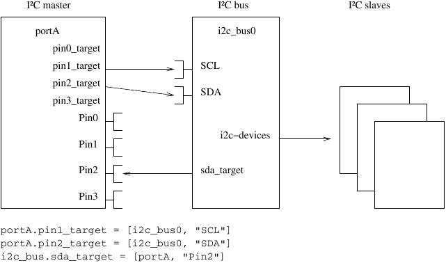
I2C have two wires, clock and data, where the data line is bidirectional. In Simics, the bidirectional line is modeled as two unidirectional signals, one going from the master to the bus, and one going from the bus to the master. The i2c-bus implements two signal ports, SCL and SDA, and provides one signal attribute sda_target for the SDA signal going from the bus to the master. The example setup in figure 7 illustrates this.