Ethernet Networking Technology Guide
This guide explains how to use Simics to simulate Ethernet networks as well as
how to connect the simulation to real networks.
This chapter describes how Simics models Ethernet networking.
Connecting simulated machines over a simulated Ethernet connection is done by
creating a link using one of the components in the eth-links module:
ethernet-cable, ethernet-hub or ethernet_switch. Any of these components
can connect to the Ethernet devices of the simulated machines. They model
Ethernet at the frame level, in that they perform delivery of complete frames
sent from one device to another, and do not model collisions or lower-level
signaling details. Each of the three Ethernet links has its own particularities:
- ethernet_cable An Ethernet cable can only be
connected to two devices, since, as a real Ethernet cable, it only has two
ends. Apart from transporting Ethernet frames back and forth, an Ethernet
cable models whether the signal is up or down.
- ethernet_hub An ethernet_hub is the simplest
Ethernet link model: all frames are broadcast to all devices connected to the
hub. It works like a traditional hub or coaxial cable.
- ethernet_switch An ethernet_switch also allows the
connection of multiple devices, but functions rather like a switch: as it
learns what MAC addresses the different devices have, it stops broadcasting
and transports the frame more selectively. This can substantially improve
simulation performance when several devices are talking on the link, and even
more so when the simulation is distributed.
As all three models work more or less at the frame level; they can be used for
any type of Ethernet connection, without limitations due to speed or technology.
Traffic sent over the link can be anything, including TCP/IP or any other
protocol stack that works on top of Ethernet. The link does not need to be
configured for the intended use.
The three components are provided in the eth-links module. They can be
manipulated in the same way as any other component: after loading eth-links,
the create-ethernet-cable/hub/switch commands are made available. They create
non-instantiated components:
simics> load-module eth-links
simics> create-ethernet-hub
Created non-instantiated 'ethernet-hub' component 'ethernet_hub0'.
The name will be automatically chosen by Simics unless it is provided as an
argument to the command:
simics> create-ethernet-hub my_ethernet_hub
Created non-instantiated 'ethernet-hub' component 'my_ethernet_hub'.
When a link component has been created, it is possible to connect the network
devices by running the connect command for each Ethernet port. For
demonstration, we will use x86 machines from the QSP-x86 package. Start the
simulation with the firststeps-multi.simics start script and run the following
commands:
simics> load-module eth-links
simics> create-ethernet-hub my_ethernet_hub
Created non-instantiated 'ethernet_hub' component 'my_ethernet_hub'
simics> connect board0.mb.sb.eth_slot my_ethernet_hub.device0
To find a connector which is not connected for ethernet_cable/hub/switch
components the get-free-connector command can be used. This command returns
the name of a free connector:
simics> my_ethernet_hub.get-free-connector
"my_ethernet_hub.device1"
Together the get-free-connector and connect commands can be used to connect
an Ethernet device to a free connector:
simics> connect (my_ethernet_hub.get-free-connector) board1.mb.sb.eth_slot
Now, when all of the components of the system are configured and connected
together, instantiate the link components:
simics> instantiate-components
It is also possible to create instantiated links with the
new-ethernet-cable/hub/switch commands, but note that this only works if there
is already at least one instantiated top-level component in the simulation.
The ethernet_switch described in the previous section complains if it receives
frames tagged with VLAN information. For VLAN the eth-links provides an IEEE
802.1Q VLAN aware switch: ethernet_vlan_switch.
This section assumes you know what VLAN is. It only shows how to configure and
use the ethernet_vlan_switch.
The VLAN switch has the same functionality as the basic Ethernet switch, but the
interface is different to handle the added complexity of VLAN. You need to add
VLAN groups to the switch before you can connect Ethernet devices to it. Each
VLAN group has its own set of connectors.
The VLAN switch is created in the same way as the other Ethernet link
components:
simics> load-module eth-links
simics> create-ethernet-vlan-switch evs
Created non-instantiated 'ethernet_vlan_switch' component 'evs'
Once the link has been created you need to add VLAN groups to it:
simics> evs.add-vlan 1
Each VLAN group adds two kinds of connectors: vlan_X_devY and
vlan_X_trunk_devY, where X is the VLAN group id and Y is an
identifier for the connector. When a connector of one kind is used the switch
automatically creates a new empty connector of the same kind with a new
identifier.
Use the vlan_X_devY connectors to connect devices which do not expect or
add VLAN tags. For example, to connect the first network port of the QSP-x86
machine created by the firststeps-multi.simics script:
simics> connect board0.mb.sb.eth_slot evs.vlan_1_dev0
Frames sent from the switch on these connections will not have any VLAN tags and
the switch will generate a warning if it receives a tagged frame on such a
connection.
Each VLAN group also has trunk connectors. On these connections the switch will
parse frames sent to the switch to find which VLAN group they should be sent to
and the switch will ensure that outgoing frames are tagged with the correct VLAN
group.
To avoid having to keep track of the connector identifiers you can use
get-free-connector to get an available non-trunk connector for a VLAN group:
simics> evs.get-free-connector 1
"evs.vlan_1_dev1"
simics> connect board1.mb.sb.eth_slot (evs.get-free-connector 1)
simics> evs.get-free-connector 1
"evs.vlan_1_dev2"
and get-free-trunk-connector to get an available trunk connector for a VLAN
group:
simics> evs.get-free-trunk-connector 1
"evs.vlan_1_trunk_dev0"
All frames that are sent over a link are delivered to the receiving devices
after a small delay. The delay is the same for every frame, and is called the
latency of the link. Each link object has a goal_latency configuration
parameter that controls the ideal latency the link wants to obtain.
Link objects are most often used to communicate between network devices using
separate clocks. Due to the way Simics handles simulated time, different clocks
are not always completely synchronized. In order to avoid nondeterministic
simulation, the link latency must be high enough that any data sent over the
link will never reach the recipient at a point in time it has already passed.
This imposes a lower boundary on the latency, called the minimum latency of
the link. The value of the minimum latency depends on the simulation setup, in
particular whether the simulation is multithreaded or distributed across several
Simics processes. See chapter Scaling
Simics of the Simics User’s Guide
for more information about links and latencies.
The latency of a link can be specified in the create-ethernet-cable/hub/switch
command as a time in seconds. If the latency of a link is set too low, it will
be automatically adjusted to the lowest value allowed by the setup when the
component is instantiated. For example, when creating two instances of the
QSP-x86 machine and connecting them to an Ethernet link with a too low
latency, Simics will adjust the latency automatically. Let us look at an example
with the firststeps-multi.simics script. It uses the new- command to create
instantiated components instead of the create- variant:
simics> load-module eth-links
simics> new-ethernet-hub goal_latency = 0.000001
Created instantiated 'ethernet_hub' component 'ethernet_hub0'
simics> connect board0.mb.sb.eth_slot ethernet_hub0.device0
simics> connect board1.mb.sb.eth_slot ethernet_hub0.device1
The effective latency of a link can be displayed by the status command
provided by the link object. The actual Ethernet links are not created until the
components are instantiated. To get access to the Ethernet link implementation,
just request the link object in the component:
simics> ethernet_hub0.link.status
Status of ethernet_hub0.link [class eth-hub-link]
=================================================

    Effective latency : 10.0 ms

    Connected devices : ('board0.mb.sb.phy', 'board0.cell')
                        ('board1.mb.sb.phy', 'board1.cell')
Note the higher effective latency the link obtained, despite a goal latency of
1us. The default latency can be adjusted using the set-min-latency command.
It is often useful to let the simulated machines use services (e.g. DHCP
service) available on the simulated network. Normally these services run on
servers connected to the network. To avoid having to set up simulated servers
just to provide them, Simics implements a service node instead.
The service_node_comp component class, available after loading the std-comp
module, provides a virtual network node that acts as a server for a number of
TCP/IP-based protocols, and as an IP router between simulated networks. It
handles both IPv4 and IPv6 protocol versions. The supported services are:
- IP based Routing (v4 and v6)
- RARP (v4)
- DHCP/BOOTP (v4) and DHCPv6 (v6)
- DNS (v4 and v6)
- FTP (v4) (see section Using FTP Service of Simics User Manual and
ftp-service class description in Simics Reference Manual)
- TFTP (v4)
- Real network connections (see chapter 3)
There can be any number of service_node_comp components, and each one can be
connected to any number of Ethernet links. In most configurations, however,
there will be a single service node. A service node can be created using the
create/new-service-node-comp commands. An example, starting with the
firststeps-multi.simics script:
simics> load-module std-comp
simics> new-service-node-comp sn0
Created instantiated 'service_node_comp' component 'sn0'
This service node can then be connected to an Ethernet link component. Note that
the service-node IP address on the link must be specified:
simics> load-module eth-links
simics> new-ethernet-hub
Created instantiated 'ethernet_hub' component 'ethernet_hub0'
simics> sn0.connect-to-link ethernet_hub0 10.10.0.1
Adding host info for IP 10.10.0.1: simics0.network.sim  MAC: 20:20:20:20:20:00
Connecting links can be done with non-instantiated components. Some commands are
only available after the service node has been instantiated, for example:
simics> sn0.list-host-info
IP         name.domain          MAC
-------------------------------------------------
10.10.0.1  simics0.network.sim  20:20:20:20:20:00
Simics’ service node can provide IP based routing between Ethernet links,
allowing machines attached to different networks to communicate with each other.
To use the routing mechanisms, simulated machines must use the IP address of
the service node as a gateway for IP based traffic. Configuring a gateway
requires system administration skills, and the exact procedure depends on the
target operating system.
Each connection of the service-node to an Ethernet link implies a default route
to that link. For example, connecting a service node with the address
192.168.0.1/24 to link1 implies that all packets matching this network and
mask combination will be routed to link1 automatically. This often solves the
most common routing needs.
In addition, the service node contains an internal IP routing table that is used
for packet routing between connected links. The routing table can be viewed
using the <service_node_comp>.route command:
simics> sn0.route
Destination  Netmask  Gateway  Link
------------------------------------
10.10.0.0    24                link0
The output is quite similar to route command available on many systems. The
destination and netmask fields specify a target that can be either a network
(i.e., a range of addresses) or a single host (with netmask 255.255.255.255).
For packets with this target as their destination, the link field specifies
the Ethernet link the packet should be sent to.
New entries can be added to the routing table with the
<service_node_comp>.route-add command. If there is a service node called sn0
connected to two links called link0 and link1, it would for example be
possible to set up routes like this:
simics> sn0.route-add 192.168.0.0 255.255.0.0 link = link0
simics> sn0.route-add 192.168.1.0/26 link = link1
simics> sn0.route-add 10.10.0.0 255.255.0.0 192.168.0.1 link0
simics> sn0.route-add 0.0.0.0 255.255.255.255 192.168.1.1 link1
simics> sn0.route
Destination  Netmask  Gateway      Link
----------------------------------------
192.168.0.0  16                    link0
192.168.1.0  26                    link1
10.10.0.0    16       192.168.0.1  link0
default               192.168.1.1  link1
The destination address and the netmask identify the target, and should be given
as strings in dotted decimal form. If the target is a single host, the netmask
should be given as "255.255.255.255".
A service node can act as a Dynamic Host Configuration Protocol (DHCP) or
Bootstrap Protocol (BOOTP) server, responding to requests from clients that
can read their network configuration from such a server. The DHCP protocol is an
extension of the BOOTP protocol, and for many uses the feature set is more or
less the same. The Simics implementation uses the same configuration for both
services.
The service node has a table that maps MAC addresses to IP addresses and domain
name. This is used to answer DHCP or BOOTP requests. The
<service_node_comp>.add-host command can add entries to this table:
simics> sn0.add-host 10.10.0.1 node1 mac="10:10:10:10:10:01"
Adding host info for IP 10.10.0.1: node1.network.sim  MAC:10:10:10:10:10:01
The <service_node_comp>.list-host-info command prints the current contents of
the table:
simics> sn0.list-host-info
IP         name.domain          MAC
-------------------------------------------------
10.10.0.0  simics0.network.sim  20:20:20:20:20:00
10.10.0.1  node1.network.sim    10:10:10:10:10:01
The <service_node_comp>.dhcp-add-pool command adds dynamic DHCP leases, from
which new clients will be automatically assigned an address on request. When an
entry from the pool is given out, the new mapping is stored in the internal host
info table, including a generated name that can be found through DNS queries. If
a DHCP client’s MAC address matches an entry in the table, it is assigned the
corresponding IP address. If there is no matching MAC address, the dynamic
address pools will be searched for an available IP address.
The DHCP implementation in service-node is simple, and might not work with all
DHCP clients.
The service node includes the functionality of a simple Domain Name Server
(DNS), that a simulated client can use to translate a host/domain name into an
IP address and vice versa. The DNS service is based on the same host table as
the DHCP service, and only answers requests for A and PTR records.
For entries in the table that will only be used to answer DNS requests, and not
for DHCP, the MAC address can be left out. The <service_node_comp>.add-host
command can be used to add table entries, and the
<service_node_comp>.list-host-info command prints the current table. By
default, all host entries will use the network.sim domain.
simics> sn0.add-host 10.10.0.1 donut
Adding host info for IP 10.10.0.1: donut.network.sim
simics> sn0.add-host 10.11.0.1 foo other.domain
Adding host info for IP 10.11.0.1: foo.other.domain
simics> sn0.list-host-info
IP         name.domain          MAC
-------------------------------------------------
10.10.0.0  simics0.network.sim  20:20:20:20:20:00
10.10.0.1  donut.network.sim    10:10:10:10:10:01
10.11.0.1  foo.other.domain
For dynamic DHCP addresses, a DNS name will be added for the new IP number, so
that any of these addresses can be found by the DNS service. When connected to a
real network, the DNS service can do external lookups for names it does not
recognize.
The service node also supports the Trivial File Transfer Protocol (TFTP, see
RFC 1350) which allows to transfer files between the host system (running the
simulation) and a simulated (target) client. TFTP is often used during network
booting, together with the BOOTP facilities, to load OS kernels and images, and
it can also be used interactively with the tftp command found on many systems.
Files transferred from the host system to the simulated client should be placed
in a directory in the Simics path. This is the standard path used by image
objects: list-directories prints its current value, while add-directory adds
a directory to the path list. The current working directory is also
automatically included.
Files transferred from the simulated client to the host end up in the current
working directory. When running Simics from the command line, this is the
directory Simics was started from.
TFTP is based on UDP, and each packet is acknowledged individually before the
transfer is allowed to continue. Depending on the latency of the link, the
transfer of large files can be slow. In that case, ensuring that the link uses
a lower latency will increase performance.
Simics provides several ways of listening to the network traffic on one, or all
Ethernet links. Simics includes ready-to-use traffic dumping capabilities, using
external network monitoring tools. It also provides an Ethernet probe and
Ethernet snooper capabilities, giving access to a programmatic interface for
listening to the network traffic.
Simics provides several commands to dump the traffic on one or several Ethernet
links. These commands use existing file formats and network monitoring tools to
present the results:
- pcap-dump The
<ethernet_link>.pcap-dump command
dumps the traffic of a specific Ethernet link to a file that can be read by
tcpdump or any compatible program like Wireshark
(https://www.wireshark.org). A global pcap-dump
also exists to dump the traffic of all Ethernet links of the simulation in the
same file.
- tcpdump The
tcpdump command works as pcap-dump,
but the traffic is redirected to a tcpdump instance running in a separate
window (for Linux only).
- wireshark The
wireshark command works as
tcpdump, but redirects the traffic to an instance of Wireshark instead.
Note that there can only be one traffic dumping tool active on the link. Simics
will automatically stop the current traffic dump and start a new one as
necessary. The pcap-dump-stop, tcpdump-stop, and wireshark-stop commands
can be used to stop the traffic dumping.
These commands can also be activated for a specific device on the link by
associating them with an existing Ethernet probe. This is described in the
Ethernet Probe section below.
The Ethernet probe provides a way to listen to traffic at a particular endpoint
of the link, that is, the probe will receive both incoming and outgoing traffic
for a particular device.
A probe is inserted using the insert-ethernet-probe command with appropriate
arguments. We will use QSP-x86 as an example machine. Please start the
simulation with the firststeps-no-network.simics start script:
simics> load-module eth-links
simics> new-ethernet-switch link0
Created instantiated 'ethernet_switch' component 'link0'
simics> connect link0.device0 board.mb.sb.eth_slot

# insert a probe between the PHY of the eth[0] device above and the link
simics> load-module eth-probe
simics> insert-ethernet-probe device = board.mb.sb.phy
Created probe 'probe0'
simics> probe0.info
Information about probe0 [class eth-probe]
==========================================

Connections:
    Port A : board.mb.sb.phy
    Port B : link0.link
At this point, the probe is ready to use. You can issue a
<eth-probe>.pcap-dump or similar command to connect an external network
monitoring tool at the probe level. The traffic will be dumped as seen from the
board.mb.sb.phy device.
You can also register your own callback to listen to the traffic going-on in the
probe, using the ethernet_probe interface provided by the probe object:
typedef enum {
        Eth_Probe_Port_A = 0,
        Eth_Probe_Port_B = 1
} eth_probe_side_t;
typedef void (*ethernet_probe_snoop_t)(lang_void *user_data,
                                       conf_object_t *probe,
                                       eth_probe_side_t to_side,
                                       const frags_t *frame,
                                       eth_frame_crc_status_t crc_status);
// END ethernet_probe_snoop_t
SIM_INTERFACE(ethernet_probe) {
        void (*attach_snooper)(conf_object_t *NOTNULL probe,
                               ethernet_probe_snoop_t snoop_fun,
                               lang_void *user_data);
        void (*attach_probe)(conf_object_t *NOTNULL probe,
                             ethernet_probe_snoop_t snoop_fun,
                             lang_void *user_data);
        void (*detach)(conf_object_t *NOTNULL probe);
        void (*send_frame)(conf_object_t *NOTNULL probe,
                           eth_probe_side_t to_side,
                           const frags_t *frame,
                           eth_frame_crc_status_t crc_status);
};

#define ETHERNET_PROBE_INTERFACE "ethernet_probe"
A complete description of this interface is provided in the API Reference
Manual, chapter Model-to-Model Interfaces, section
ethernet_probe.
What we are interested in at this point is to register a snooper callback that
will only listen to traffic:
simics> python-mode
# a callback that does nothing but print a warning
def callback(user_data, probe, to_side, packet, crc_status):
    if to_side == Eth_Probe_Port_A:
        print('packet going to device')
    else:
        print('packet going to network')
conf.probe0.iface.ethernet_probe.attach_snooper(callback, None)
.........
simics>>> (Ctrl-D)
simics> continue
packet going to network
packet going to network
[...]
The probe can also drop, modify or inject packets. This is described in the next
part Injecting and Modifying Network
Traffic.
Ethernet links provide a special interface to listen to all traffic on the link
via a function callback. This makes it possible to write simple traffic dumping
scripts with customized output.
/* <add-type id="ethernet_link_snoop_t"></add-type> */
typedef void (*ethernet_link_snoop_t)(lang_void *user_data,
                                      conf_object_t *clock,
                                      const frags_t *packet,
                                      eth_frame_crc_status_t crc_status);
SIM_INTERFACE(ethernet_snoop) {
        conf_object_t *(*attach)(conf_object_t *NOTNULL link,
                                 conf_object_t *clock,
                                 ethernet_link_snoop_t snoop_fun,
                                 lang_void *user_data);
};
#define ETHERNET_SNOOP_INTERFACE "ethernet_snoop"
This interface is implemented by Ethernet link objects. It is used to attach
snoop functions to the link. The snoop function will receive all traffic
going over the link.
This interface should only be used for inspection, and never as part of the
actual simulation. The snoop functions must not affect the simulation in any
way.
The clock parameter tells the link on which clock to post the
events that call the snoop function. The snoop function will be called at
the delivery time of the network packet, which means that it will be called
at the same time as any Ethernet devices attached to the same clock that
receives packets from the same link.
Snooped frames with a matching CRC will contain the correct frame check
sequence.
The user_data parameter is passed to the snoop function every
time it is called.
We will use the QSP-x86 as an example. Please start the simulation with the
firststeps-no-network.simics start script, a simple script callback could be
written as follows:
simics> load-module eth-links
simics> new-ethernet-switch link0
Created instantiated 'ethernet_switch' component 'link0'
simics> connect link0.device0 board.mb.sb.eth_slot
simics> python-mode
# a callback that does nothing but print a warning
def callback(user_data, clock, packet, crc_status):
    print("packet received in snooper")
# callback registration on link0, using the CPU as clock object
ep = conf.link0.link.iface.ethernet_snoop.attach(
    conf.board.mb.cpu0.core[0][0], callback, None)
.........
simics>>> (Ctrl-D)
simics> continue
packet received in snooper
packet received in snooper
[...]
The endpoint object returned by the attach() function can be destroyed as any
time using SIM_delete_object(), ending the capture. Snooper endpoints are used
by the external monitoring tools system described in the previous section to
feed to the tools the packets passing on the links.
Ethernet links have built-in commands for monitoring and viewing Ethernet
traffic over the link. This feature is an easier approach to quickly get a view
of the status over the link. Same as in previous examples, start Simics with the
firststeps-no-network.simics start script and enter the following commands:
simics> run-script "targets/qsp-x86/firststeps-no-network.simics"
simics> load-module eth-links
simics> new-ethernet-switch link0
simics> connect link0.device0 board.mb.sb.eth_slot
simics> link0.start-link-monitor
simics> r 75 s
Autologin as "simics" was done on "board.mb.sb.com[0] - serial console".
simics> link0.view-link-monitor
Link link0:
00:17:a0:00:00:00 (::) sent 3 packets to 33:33:ff:00:00:00
00:17:a0:00:00:00 (fe80::217:a0ff:fe00:0) sent 1 packets to 33:33:ff:00:00:00
Each line in the output shows that Ethernet source with IP (*) sent # packets to
Ethernet destination. The number of packets is accumulated for the combination
of source and destination. At any time it is possible to stop the monitoring by
issuing stop-link-monitoring.
It is possible to put breakpoints on a certain Ethernet source, destination or
packet type and also as a trace. Here we set up Simics as before:
Break:
simics> run-script "targets/qsp-x86/firststeps-no-network.simics"
simics> load-module eth-links
simics> new-ethernet-switch link0
Created instantiated 'ethernet_switch' component 'link0'
simics> connect link0.device0 board.mb.sb.eth_slot
simics> bp.network.break link0.link src_mac = "00:17:a0:00:00:00"
Breakpoint 2: link0.link will break on src_mac = 00:17:a0:00:00:00
simics> r
[link0.link] Breakpoint 2: link0.link src = 00:17:a0:00:00:00, dst = 33:33:ff:00:00:00, ether_type = 86dd, ip = ::
simics> bp.network.trace link0.link eth_type = 8000
3
Trace:
simics> run-script "targets/qsp-x86/firststeps-no-network.simics"
simics> load-module eth-links
simics> new-ethernet-switch link0
Created instantiated 'ethernet_switch' component 'link0'
simics> connect link0.device0 board.mb.sb.eth_slot
simics> bp.network.trace link0.link dst_mac = "ff:ff:ff:ff:ff:ff"
2
simics> r 100 s
[bp.network trace] [trace:2] link0.link matched  dst_mac = ff:ff:ff:ff:ff:ff
Simics comes with a eth-injector class that takes a pcap format file and
injects the packets described in the file into the simulated network.
Each packet in a pcap file has a time stamp that usually is the absolute time
when the packet was recorded. The eth-injector starts injecting the first
packet of the pcap file directly after the start command has been run. The
consecutive packets are injected after an amount of virtual time that is equal
to the difference in time stamp between that packet and the first packet of the
pcap file. If the packet cannot be injected because of bandwidth limitations, it
is ignored. Incoming packets are ignored as well.
It is common that the CRC of Ethernet frames are not recorded in pcap files. In
Simics, the whole Ethernet frame has to be present for a correct simulation
result. The -no-crc option of the <eth-injector>.start command can be used
to tell the injector that the pcap file contains no CRC. The injector then adds
a CRC to each frame that Simics will handle as if it was correct. By not using
the -no-crc option the frames in the pcap file are injected as they were
recorded, without any modification.
The eth-injector can be connected to an Ethernet link like any other Ethernet
device. It can also be connected directly to another Ethernet device without the
need to have a link between the device and the eth-injector.
The following example creates a new eth-injector, connects it to an already
existing ethernet_switch of name ethernet_switch0 and starts packet playback
from a file named test.pcap:
simics> load-module eth-injector-comp
simics> new-eth-injector-comp name = inj0
Created instantiated 'eth_injector_comp' component 'inj0'
simics> connect ethernet_switch0.link inj0.link
simics> inj0.injector.start file = test.pcap
The section Observing Network Traffic
explained how to use an Ethernet probe to listen to the incoming and outgoing
traffic of a device connected on an Ethernet link. A probe can also be used to
modify this traffic by dropping and changing existing packets, or injecting new
ones.
typedef enum {
        Eth_Probe_Port_A = 0,
        Eth_Probe_Port_B = 1
} eth_probe_side_t;
typedef void (*ethernet_probe_snoop_t)(lang_void *user_data,
                                       conf_object_t *probe,
                                       eth_probe_side_t to_side,
                                       const frags_t *frame,
                                       eth_frame_crc_status_t crc_status);
// END ethernet_probe_snoop_t
SIM_INTERFACE(ethernet_probe) {
        void (*attach_snooper)(conf_object_t *NOTNULL probe,
                               ethernet_probe_snoop_t snoop_fun,
                               lang_void *user_data);
        void (*attach_probe)(conf_object_t *NOTNULL probe,
                             ethernet_probe_snoop_t snoop_fun,
                             lang_void *user_data);
        void (*detach)(conf_object_t *NOTNULL probe);
        void (*send_frame)(conf_object_t *NOTNULL probe,
                           eth_probe_side_t to_side,
                           const frags_t *frame,
                           eth_frame_crc_status_t crc_status);
};

#define ETHERNET_PROBE_INTERFACE "ethernet_probe"
A complete description of this interface is provided in the API Reference
Manual, chapter Model-to-Model Interfaces, section
ethernet_probe.
What we are interested in now is to register a probe callback that will be
allowed to modify the traffic:
simics> python-mode
# a callback that drops all outgoing packets
def callback(user_data, probe, to_side, packet, crc_status):
    if to_side == Eth_Probe_Port_A:
        print('dropping incoming packet')
    else:
        print('forwarding outgoing packet')
        probe.iface.ethernet_probe.send_frame(to_side, packet, crc_status)
conf.probe0.iface.ethernet_probe.attach_probe(callback, None)
.......
simics>>> (Ctrl-D)
simics> continue
forwarding outgoing packet
forwarding outgoing packet
[...]
When a callback is registered as a probe, it takes responsibility for
forwarding packets it receives. It is also allowed to drop them, modify them,
modify their CRC status or inject new packets. For example, it could duplicate
outgoing packets, inject errors, etc. Note that if your callback modifies the
simulation in this manner, you may need to create an object representing the
changes’ state engine to make sure the simulation can be checkpointed and stays
deterministic.
Connecting a simulator to a real network opens many new possibilities. For
example, it makes it easy to download files to the simulated machines using FTP,
to access the simulated machines remotely through telnet, or to test software on
simulated machines against real machines.
Simics provides three kinds of real-network connections. This chapter will go
through all of them in details, with numerous examples. Section
3.1 starts by explaining the preparatory steps for all
the examples presented afterwards. Section 3.2 goes
through all three kinds of real-network connections, how they are set up and
what they provide.
Some real-network connections require specific configuration on the host system:
these are covered in section 3.3. Section
3.4 describes how to select the correct host
interface when running on a host with multiple Ethernet interfaces.
Finally, section 3.5 describes how to tune real
network connections to improve their performance, and section
3.6 contains a troubleshooting guide to help
diagnose problems.
Connecting a simulated network to a real network requires some knowledge of
network administration issues.
All the examples in section 3.2 use the simulated
QSP-x86 machine from the First Steps tutorial. Start the
firststeps-no-network.simics configuration and boot the machine. Then, to save
time when trying several examples, save a checkpoint. This checkpoint can be
used instead of launching and booting QSP-x86 for each example. When idling,
QSP-x86 runs faster than real time, which means that it can time out faster
than expected, unless real time mode is turned on with enable-real-time-mode.
Not all kinds of connections with real network, or with real file systems,
will continue to work properly if you pause the simulation for a shorter or
lengthier time. This applies to most stateful connections, for example NFS,
TCP, etc.
For the same reason, not all kinds of connections with the real world can be
saved in a checkpoint and successfully restored at a later time. Hence, make a
habit to disconnect such services before pausing the simulation, or before
saving a checkpoint.
Some of the examples involve using telnet to connect to the simulated machine.
On both Linux and Windows, a telnet binary is provided and can be used directly
in a terminal or in a Command-Line prompt, respectively. The output on Windows
may be slightly different from the output given in the examples.
In the examples, the simulated machine sometimes needs to be reconfigured. Since
it is running Linux, the appropriate Linux configuration commands are indicated.
Other operating systems should be configured similarly, but the commands may of
course differ.
Finally, in all examples, the host machine where Simics is running has the IP
address 10.0.0.129 and the real host that communicates with the simulated
network has the IP address 10.0.0.240. These addresses should be replaced as
necessary. QSP-x86 uses its default IP address 10.10.0.40.
The examples assume that there is a host on the real network that accepts telnet
connections. Check that it is possible to telnet from the simulation host to the
other real host. Just run telnet ip at a command-line, where ip is the IP
address of the other real host. If that does not work, the simulated machine
will not be able to connect to the real host either.
If there is no host that accepts telnet connections on the network, the
connection can be tested with a web server on port 80 instead, by entering GET / HTTP/1.0 and a blank line. This should return the HTML content of the start
page of the server. Here www.google.com is used:
~# telnet www.google.com 80
Trying 64.233.161.104...
Connected to 64.233.161.104.
Escape character is '^]'.
GET / HTTP/1.0

HTTP/1.0 302 Found
Location: http://www.google.se/cxfer?c=PREF%3D:TM%3D1118841789:S%3DumCVbug84n5uBWAo&prev=/
Set-Cookie: PREF=ID=a5e237e2402bdcac:CR=1:TM=1118841789:LM=1118841789:S=HQ3jOc8_1peVGj98; expires=Sun, 17-Jan-2038 19:14:07 GMT; path=/; domain=.google.com
Content-Type: text/html
Server: GWS/2.1
Content-Length: 214
Date: Wed, 15 Jun 2005 13:23:09 GMT
Connection: Keep-Alive

<HTML><HEAD><TITLE>302 Moved</TITLE></HEAD><BODY>
<H1>302 Moved</H1>
The document has moved
<A HREF="http://www.google.se/">here</A>.
</BODY></HTML>
Connection closed by foreign host.
~#
Make sure that the telnet or web server is on the same IP subnet as the
simulation host, since it may not be possible to access other subnets, depending
on what real-network connection is in use.
There are three kinds of connections between simulated networks and real
networks in Simics. The next paragraphs describe how they work, and their
advantages and drawbacks.
All connection types except port forwarding require low-level access to the
simulation host’s Ethernet interfaces, and therefore require administrative
privileges to set up. However, administrative privileges are, in most cases, not
needed once the low-level access has been set up. See section
3.3 for details.
- Port forwarding Port forwarding is the easiest
connection type to set up for simple usage. It does not require administrative
privileges nor any configuration on the simulation host or on the other hosts.
However, port forwarding is limited to TCP and UDP traffic. Other traffic, for
example, ping packets that use the ICMP protocol, will not pass through the
connection. Since port forwarding uses ports on the simulation host it is not
possible to use incoming ports that are already used by the simulation host, or
ports below 1024 without administrative privileges.
Each incoming TCP port, and each incoming or outgoing UDP port require a
separate forwarding rule. Therefore, for an application that uses many ports, or
random ports, configuration can become cumbersome or nearly impossible without
complex communication. Outgoing TCP connections on many or random ports can be
handled by NAPT, so that is not a problem.
Port forwarding allows communication between the simulated machines, the
simulation host and other hosts on the real network.
- Ethernet bridging connection With an Ethernet
bridging connection, the simulated machines appear to be directly connected to
the real network. The connection allows any kind of Ethernet traffic between
the simulated and real networks. Usually IP addresses from the IP subnet of
the real network are used by the simulated machines, in which case nothing
needs to be configured on the real hosts on the real network. However, the
simulation host cannot be accessed from the simulated machines using an
Ethernet bridging connection.
To use Ethernet bridging, the simulation host needs to be set up for TAP access
as described in section 3.3.
- Host connection With a host connection, the
simulation host is connected to a simulated network, allowing any kind of
Ethernet traffic between the simulation host and the simulated machines.
Host connections also support IP forwarding. When using IP forwarding, the
operating system of the host routes IP traffic between the real and simulated
networks. As above, routes should be configured between the simulated and real
networks to make it work.
To use host connections, the host needs to be set up for TAP access as described
in section 3.3.1.
> [!NOTE]
> A raw packet with length X bytes sent from the simulation host through the
> real network device into the simulated target will have 4 Bytes of
> FCS(frame check sequence) appended. The target machine will actually
> receive a packet of length X+4 bytes. The NIC model on the target machine
> usually checks and strips the FCS bytes before it is seen by any software.
> A raw packet that originates from the target will have an FCS calculated
> and appended by the NIC model. The real network device will then check the
> FCS and strip it before sending to the simulation host interface (TAP
> interface).
Figure 1. Comparison of real-network connections
| Port Forwarding | Ethernet Bridge | Host Connection |
|---|
| Need admin rights for config. | no | yes | yes |
| Need admin rights to run | no | no | no |
| Need real IP available | no | yes | no |
| Support UDP/TCP | yes | yes | yes |
| Restrict TCP/UDP ports | yes | no | no |
| Support all IPv4 | no | yes | yes |
| Support all Ethernet | no | yes | yes |
The table 1 recapitulates the advantages and drawbacks of
each type of connection. Basically, for simple TCP services like FTP, HTTP or
telnet, port forwarding is the way to go. If port forwarding does not suffice
and if there are available IP addresses on the IP subnet of the real network, or
for network protocols other than IPv4, Ethernet bridging is another possibility.
Finally, if access to the simulated machines from the simulation host is
required, but port forwarding is not sufficient, host connection might be the
solution.
All commands that create a connection to the real network start with the prefix
connect-real-network-, with different suffixes depending on the connection
type. They come in two variants.
For each connection type there is a global command that assumes that there is at
most one Ethernet link object. If there is no Ethernet link object, a default
ethernet_switch is created. All Ethernet interfaces of all simulated machines
in the Simics process are then automatically connected to the new Ethernet
switch, and the Ethernet switch is connected to the real network. This is an
easy way to connect all simulated machines in the Simics process to the real
network with a single command. For example, to connect all simulated machines to
the real network using an Ethernet bridging connection, just type in the global
command connect-real-network-bridge.
For a more complex simulated network setup, not all simulated Ethernet
interfaces will be connected to the same network. In that case, create first the
simulated network setup, and then connect specific Ethernet links to the real
network. For each connection type, there is a command with the same name as the
global command that can be run on a specific Ethernet link object to connect it
to the real network. For example, with an Ethernet link object named
ethernet_hub0, use the command ethernet_hub0.connect-real-network-bridge to
create an Ethernet bridging connection between that particular link and the real
network.
The commands related to port forwarding are an exception to this rule. They do
not come in variants that can be run on Ethernet links objects, but instead have
an ethernet-link argument that can be used to specify a link.
Port forwarding forwards traffic on TCP and UDP ports between the simulated
network and the real network. It also allows forwarding DNS queries from the
simulated network to the real network. Port forwarding can be used with any kind
of IP network on the host, it is not limited to Ethernet networks.
Port forwarding is probably the easiest way to access the real network for
simple TCP or UDP connectivity, for example, telnet or FTP usage. Port
forwarding is easy to set up. Simics does not need administrative privileges to
run port forwarding, and neither the simulation host nor any other host needs to
be configured in any way.
Port forwarding is managed by a service node connected to an Ethernet link. It
is the service node that listens for traffic on both the real and simulated
networks and forwards it to the other side. All port forwarding commands except
connect-real-network therefore take as argument an Ethernet link with a
connected service node.
There are really four distinct parts to Simics’s port forwarding solution:
forwarding of specific ports from the real network to the simulated network,
forwarding of specific ports from the simulated network to the real network,
NAPT from the simulated network to the real network, and forwarding of DNS
queries to the real network.
There is also a convenience command named connect-real-network that
automatically sets up NAPT for outgoing traffic, forwarding of DNS queries to
the real network, and incoming port forwarding for some common services. If
there is no Ethernet link object, one is created and set up.
The list-port-forwarding-setup command describes the current port forwarding
setup: it will list all incoming and outgoing ports, as well as the NAPT and DNS
forwarding status.
Pinging between the simulated network and the real network will not work when
using port forwarding, so ping should not be used to test if the connection is
working. Ping uses the ICMP protocol, but only TCP and UDP traffic is
supported with port forwarding.
The connect-real-network command is a convenience command that sets up NAPT
for outgoing traffic, enables forwarding of DNS queries to the real network, and
opens incoming ports for FTP, HTTP and telnet to a simulated machine. This is an
easy way to get inbound and outbound access for common services on a simulated
machine.
The command requires a target-ip argument that specifies the IP address of the
simulated machine that should be targeted by the incoming traffic. If there are
multiple simulated machines, connect-real-network can be run once for each
machine. Simics will select different ports on the simulation host for the
incoming services for each simulated machine, and the selected ports are printed
in the Simics console.
The connect-real-network command does not require an Ethernet link as
argument, unless there is more than one in the simulation. If there is no
Ethernet link or service node, they will be created automatically.
The connect-real-network allows us to set up all connections that are needed
for most simple real network uses with one simple command. We can start from the
checkpoint prepared in section 3.1, and then run the
connect-real-network command with the IP address 10.10.0.40, which is the
default address of QSP-x86:
simics> connect-real-network 10.10.0.40
No Ethernet link found, created default_eth_switch0.
Connected board.mb.sb.eth_slot to default_eth_switch0
Created instantiated 'service_node_comp' component 'default_service_node0'
Connecting 'default_service_node0' to 'default_eth_switch0' as 10.10.0.1
NAPT enabled with gateway 10.10.0.1/24 on link default_eth_switch0.link.
NAPT enabled with gateway fe80::2220:20ff:fe20:2000/64 on link default_eth_switch0.link.
Host TCP port 4021 -> 10.10.0.40:21
Host TCP port 4022 -> 10.10.0.40:22
Host TCP port 4023 -> 10.10.0.40:23
Host TCP port 4080 -> 10.10.0.40:80
Real DNS enabled at 10.10.0.1/24 on link default_eth_switch0.link.
Real DNS enabled at fe80::2220:20ff:fe20:2000/64 on link default_eth_switch0.link.
The output shows that an ethernet_switch and a service_node_comp components
have been automatically created and connected to the simulated machine. NAPT,
DNS forwarding, and incoming port forwarding for FTP, HTTP and telnet have also
been enabled.
Now start the simulation. Since we gave the service node the IP address
10.10.0.1, QSP-x86 should be configured with 10.10.0.1 as default gateway:
~# route add default gw 10.10.0.1
It should now be possible to telnet from the simulated machine to hosts on the
real network. In this case, we telnet to a machine with IP address 10.0.0.240;
replace this address with any host answering to telnet on the network:
~# telnet 10.0.0.240
Trying 10.0.0.240...
Connected to 10.0.0.240.
Escape character is '^]'.


SunOS 5.9

login: joe
Password:
Sun Microsystems Inc.    SunOS 5.9       Generic May 2002
$ exit
Connection closed by foreign host.
~#
QSP-x86 can be configured to use the service node as DNS server and use it to
look up real DNS names. To do that, add the line nameserver 10.10.0.1 in the
file /etc/resolv.conf on the simulated machine:
~# echo nameserver 10.10.0.1 > /etc/resolv.conf
It should now be possible to look up the addresses of real hosts on the
simulated machine, for example, https://gnu.org. QSP-x86
does not have the tools to perform DNS lookups. Instead, verify that DNS works
by connecting to a real server by name:
~# telnet gnu.org 80
GET /
<?xml version="1.0" encoding="ISO-8859-1"?>
<!DOCTYPE html PUBLIC "-//W3C//DTD XHTML 1.0 Strict//EN"
  "http://www.w3.org/TR/xhtml1/DTD/xhtml1-strict.dtd">
<html xmlns="http://www.w3.org/1999/xhtml" lang="en" xml:lang="en">
<head>
<title>Server error!</title>
[...]
Connection closed by foreign host.
~#
FTP, HTTP and telnet servers running on the simulated machine should also be
accessible. QSP-x86 runs both a telnet and a HTTP server. Just use port 4023
and 4080 instead of 23 and 80. The exact ports of the host these services are
mapped to varies if the default ports are already in use. Look at the output
from the connect-real-network above for the port numbers to use.
The connect-real-network-port-in command sets up port forwarding from a port
on the host machine to a specific port on a simulated machine. It takes three
required arguments: ethernet-link, target-ip and target-port, that specify
the Ethernet link, IP address and port the traffic should be forwarded to.
An IP address and preferred port can be selected for incoming traffic on the
simulation host using the host-ip and host-port arguments. If these
arguments are not provided, Simics will select a port automatically and print it
on the Simics console, and receive all IPv4 traffic (i.e., IP 0.0.0.0) from that
port. In order to forward multicast traffic, specify that multicast address
(e.g., specify 239.255.255.253 to forward IPv4 SLP traffic).
The connect-real-network-port-in command can also take the flags -tcp and
-udp, which specify whether forwarding is set up for a TCP or a UDP port. If
neither is provided, forwarding will be set up for both the TCP and UDP ports.
Also, with the optional -preserve-ip flag, the source IP is preserved through
a NAT layer (for TCP only).
The service node acts as a proxy for incoming traffic, so to initiate a
connection to a specific port on the simulated machine, the real machine should
contact the corresponding open port on the simulation host. The simulation host
is not a gateway to the simulated network.
Any UDP packets sent to a port on the simulation host are forwarded to the
specified port and IP address on the simulated network. For the simulated
machine to be able to return UDP packets to the real network, a separate
forwarding rule must be set up using the connect-real-network-port-out
command.
Any TCP connections to the port on the simulation host are forwarded to the
specified port and IP address on the simulated network. Since TCP connections
are two-ways, once a connection has been established, data can be sent in both
directions.
You will probably have to manually add the incoming ports to your host based
software firewall if you want to access the simulated network from another
machine. Tracking down network problems when you forget to update the firewall
is annoying as the packets tend to get dropped silently without a log.
The FTP protocol needs to open additional ports when transferring files. Simics
handles this by automatically opening outgoing ports for FTP when needed, so FTP
will work as long as it is in active mode.
QSP-x86 runs sshd on port 22. We can now set up a port forwarding rule that
allows us to access the ssh service from the real network. Start from the
checkpoint, create an Ethernet link and service node, connect the simulated
machine to the Ethernet link and run the connect-real-network-port-in command
like this:
simics> load-module eth-links
simics> new-ethernet-switch switch0
Created instantiated 'ethernet_switch' component 'switch0'
simics> new-service-node-comp sn0
Created instantiated 'service_node_comp' component 'sn0'
simics> sn0.connect-to-link switch0 10.10.0.1
Adding host info for IP 10.10.0.1: simics0.network.sim  MAC: 20:20:20:20:20:00
simics> connect board.mb.sb.eth_slot switch0.device1
simics> connect-real-network-port-in ethernet-link = switch0 target-ip = 10.10.0.40 target-port = 22 host-port = 2022 -tcp
Host TCP port 2022 -> 10.10.0.40:22
simics> enable-real-time-mode
QSP-x86 uses the IP address 10.10.0.40 and the ssh service runs on TCP port
22. We use port 2022 on the simulation host, but any free port can be used. The
last command slows down QSP-x86 to avoid time-outs.
Start the simulation, then start a ssh from a real host to the ssh service port
of the simulated machine by connecting to port 2022 of the simulation host. In
our case, we do the ssh on the simulation host itself; replace localhost with
the IP address of the simulation host if running ssh from another machine:
host:~$ ssh -p 2022 -l root localhost
The authenticity of host '[localhost]:2022 ([127.0.0.1]:2022)' can't be established.
ECDSA key fingerprint is 62:7e:eb:4d:6d:cb:ae:0f:a0:a9:44:cc:0d:59:ce:52.
Are you sure you want to continue connecting (yes/no)? yes
Warning: Permanently added '[localhost]:2022' (ECDSA) to the list of known hosts.
Last login: Mon Jan 18 10:34:08 2016
~# ls /
bin  boot  dev  disk2  etc  home  host  lib  lib64  lost+found  media  mnt  proc  run  sbin  sys  tmp  usr  var  www
~# exit
logout
Connection to localhost closed.
Note that if you restart the simulated machine, you need to remove the line
starting with ‘[localhost]:2022’ in host file ~/.ssh/known_hosts to login
with ssh again.
The connect-real-network-port-out command sets up port forwarding from a port
on a service node to a specific port on a host on the real network. It takes
four required arguments: service-node-port ethernet-link, target-ip and
target-port, that specify the port on the service node that will forward
traffic to the target, the Ethernet link the service node is connected to, and
the real IP address and port to which the traffic should be forwarded.
The command can optionally take the flags -tcp and -udp, to specify whether
the forwarding should be set up for a TCP or UDP port. If neither is provided,
forwarding will be set up for both the TCP and UDP port.
The service node acts as a proxy for outgoing traffic, so to initiate a
connection to a port on a host on the real network, the simulated machine should
connect to the corresponding mapped port on the service node. The service node
is not a gateway to the real network.
Any UDP packets sent to a port on the service node are forwarded to the
specified port and IP address on the real network. For the real host to be able
to return UDP packets to the simulated network, a separate forwarding rule must
be set up using the connect-real-network-port-in command.
Any TCP connections to the port on the service node are forwarded to the
specified port and IP address on the real network. Since TCP connections are
two-ways, once a connection has been established data can be sent in both
directions.
By setting up forwarding from a port on a service node to port 22 of a host on
the real network, it should be possible to ssh to the real host by connecting to
the port on the service node from QSP-x86. We can start from the checkpoint we
prepared in section 3.1, and create an Ethernet link
and a service node, connect the simulated machine to the Ethernet link and run
the connect-real-network-port-out command. Here we use a host on the real
network with IP address 10.0.0.240, replace it with the IP address of a real
host on the network:
simics> load-module eth-links
simics> new-ethernet-switch switch0
Created instantiated 'ethernet_switch' component 'switch0'
simics> new-service-node-comp sn0
Created instantiated 'service_node_comp' component 'sn0'
simics> sn0.connect-to-link switch0 10.10.0.1
Adding host info for IP 10.10.0.1: simics0.network.sim  MAC: 20:20:20:20:20:00
simics> connect board.mb.sb.eth_slot switch0.device1
simics> connect-real-network-port-out service-node-port = 2222 ethernet-link = switch0 target-ip = 10.0.0.240 target-port = 22 -tcp
10.10.0.1 TCP port 2222 on link switch0.link -> host 10.0.0.240:22
ff02::1:2 TCP port 2222 on link switch0.link -> host 10.0.0.240:22
simics> enable-real-time-mode
Now start the simulation. We used the IP address 10.10.0.1 and the port 2222 for
the service node, so we should be able to ssh to the real host by connecting to
port 2222 of 10.10.0.1 from QSP-x86:
~# ssh 10.10.0.1 -p 2222
The authenticity of host '[10.10.0.1]:2222 ([10.10.0.1]:2222)' can't be established.
ECDSA key fingerprint is 39:a4:cb:1c:54:4b:bd:86:9f:d1:1b:6d:a6:43:e9:f4.
Are you sure you want to continue connecting (yes/no)? yes
Warning: Permanently added '[10.10.0.1]:2222' (ECDSA) to the list of known hosts.
10.10.0.1's password:
Last login: Thu May 19 09:59:33 2016 from 127.0.0.1
host:~$ ls /
bin   dev  home  lib64       media  opt   root  sbin  sys  usr
boot  etc  lib   lost+found  mnt    proc  run   srv   tmp  var
The connect-real-network-napt command sets up NAPT (network address port
translation, also known as just NAT or network address translation) between
the simulated network and the real network. With NAPT enabled, the service node
will act as a gateway on the simulated network and automatically mediate TCP
connections to the real network.
The connect-real-network-napt only has one required argument, ethernet-link,
that specifies the Ethernet link that should be connected to the real network.
The simulated machines must be configured to use the service node as gateway for
the real network, so that it is able to capture the outgoing traffic. The
simulated machines will then be able to access hosts on the real network using
their real IP addresses. By combining NAPT with DNS forwarding, described in
section 3.2.1.5, the real DNS names of hosts on the real network
can be used as well.
The NAPT setup is not specific to a simulated machine, so
connect-real-network-napt needs only to run once for each Ethernet link, and
all simulated machines on the link get outbound access.
Since NAPT only allows new TCP connections to be opened from the simulated
network to the real network, and the FTP protocol need to open new ports when
transferring files, passive mode FTP should be used when connecting to an FTP
server on a host on the real network from a simulated machine. An alternative is
to use the FTP server implemented in the Simics service-node and avoid the need
to connect to a real network.
To try NAPT, we can start from the checkpoint we prepared in section
3.1, create an Ethernet link and service node, connect
the simulated machine to the Ethernet link and run the
connect-real-network-napt command like this:
simics> load-module eth-links
simics> new-ethernet-switch switch0
Created instantiated 'ethernet_switch' component 'switch0'
simics> new-service-node-comp sn0
Created instantiated 'service_node_comp' component 'sn0'
simics> sn0.connect-to-link switch0 10.10.0.1
Adding host info for IP 10.10.0.1: simics0.network.sim  MAC: 20:20:20:20:20:00
simics> connect board.mb.sb.eth_slot switch0.device1
simics> connect-real-network-napt ethernet-link = switch0
NAPT enabled with gateway 10.10.0.1 on link switch0.link
NAPT enabled with gateway fe80::2220:20ff:fe20:2000/16 on link switch0.link
simics> enable-real-time-mode
The simulated machine should be configured to use the service node as its
default gateway:
~# route add default gw 10.10.0.1
The enable-real-dns and disable-real-dns commands of the service node enable
and disable forwarding of DNS requests to the real network by a service node.
This allows simulated machines to look up names and IP addresses of hosts on the
real network, using the service node as DNS server.
To try DNS forwarding, we can start from the checkpoint we prepared in section
3.1, and create an Ethernet link and a service node,
connect the simulated machine to the Ethernet link and run the enable-real-dns
command like this:
simics> load-module eth-links
simics> new-ethernet-switch switch0
Created instantiated 'ethernet_switch' component 'switch0'
simics> new-service-node-comp sn0
Created instantiated 'service_node_comp' component 'sn0'
simics> sn0.connect-to-link switch0 10.10.0.1
Adding host info for IP 10.10.0.1: simics0.network.sim  MAC: 20:20:20:20:20:00
simics> connect board.mb.sb.eth_slot switch0.device1
simics> sn0.enable-real-dns
Real DNS enabled
simics> enable-real-time-mode
To tell QSP-x86 to use the service node as DNS server, the line nameserver 10.10.0.1 is needed in the file /etc/resolv.conf:
~# echo nameserver 10.10.0.1 > /etc/resolv.conf
Simics can act as a bridge between simulated Ethernet networks and the real
Ethernet networks of the host. With this type of connection, the simulated
machines will appear as directly connected to the real network, both to the
simulated machines and to the hosts on the real network. For that reason, the
simulated machines should be configured with IP addresses from the same subnet
as the real hosts.
Since the simulated machines appear to be located on the real network, there is
no need to configure routes on real hosts that communicate with it. They can
find the simulated machines by sending ARP requests, just like they would find
other real hosts.
When using a bridged connection, it is recommended to use a dedicated host
network interface for the bridge, not the interface that the host uses for
general network access. Otherwise, special configuration of the bridge interface
is necessary for any kind of network access for the host. The details about this
configuration will not be covered in this manual. See section
3.3 for how to set up TAP access.
To create a bridged connection to the real network, use the
connect-real-network-bridge command. It takes an interface argument that
specifies which host TAP interface that should be used.
This example assumes that the simulation is starting from the checkpoint
prepared in section 3.1, and that a TAP bridge has
been set up as described in section 3.2.2.2.
To set up an Ethernet bridging connection between the real network and the
simulated network, run the connect-real-network-bridge command. This will
automatically create an Ethernet link, connect it to the simulated machine and
set up bridging to the real network:
simics> connect-real-network-bridge
No Ethernet link found, created default_eth_switch0.
Connected board.mb.sb.eth_slot to default_eth_switch0
[rn0.rn info] Connecting to existing TAP device 'sim_tap0'
'default_eth_switch0' connected to real network.
When using Ethernet bridging, the simulated machine should be configured with an
unused IP address and netmask from the real network. In this case we use
10.0.0.241 and 255.255.255.0. Replace it with an unused IP address and netmask
from the real network:
~# ifconfig eth0 10.0.0.241 netmask 255.255.255.0
As the target machine will appear as a real machine in the net, its gateway
and DNS server should be correctly set according to the host settings, this
step can be verified through pinging the gateway and DNS server IP. In some
corner conditions, it’s worth trying to reset (disable and then enable) the
target Ethernet adapter if the gateway or DNS server are unreachable.
The simulated machine is now connected to the real network. Any kind of IP
traffic is bridged between the simulated network and the real network. It should
be possible to ping any real host from the simulated machine. Replace
10.0.0.240 with the address of a host on the real network:
~# ping 10.0.0.240 -c 3
PING 10.0.0.240 (10.0.0.240): 56 data bytes
64 bytes from 10.0.0.240: seq=0 ttl=64 time=10.285 ms
64 bytes from 10.0.0.240: seq=1 ttl=64 time=0.349 ms
64 bytes from 10.0.0.240: seq=2 ttl=64 time=0.323 ms

--- 10.0.0.240 ping statistics ---
3 packets transmitted, 3 packets received, 0% packet loss
round-trip min/avg/max = 0.323/3.652/10.285 ms
Of course, it should also be possible to ping the simulated machine from the
real host.
Running traceroute on the simulated machine shows that it is connected
directly to the real network; there are no routers between it and the real host.
Again, replace 10.0.0.240 with a host on the real network:
~# traceroute 10.0.0.240
traceroute to 10.0.0.240 (10.0.0.240), 30 hops max, 38 byte packets
 1  10.0.0.240 (10.0.0.240)  10.106 ms  0.371 ms  0.347 ms
If the IP address of the simulated machine itself is printed and !H is printed
after the response times, it means the simulated machine cannot reach the real
host, and the configuration is incorrect.
To use TAP access with the connect-real-network-bridge command, the operating
system must be configured to act as a bridge between the virtual interface and
the real interface. Follow the steps below to set it up.
When setting up bridging between a TAP interface and a real Ethernet
interface, the host will no longer accept traffic on the real interface. All
connections the host has open on the interface will be lost. One consequence
of this is that if this is being done from a remote console, the connection
might be lost before the bridge is fully configured. We therefore strongly
recommend that bridging is only set up on dedicated host interfaces.
-
Create a TAP interface, as described in section
3.3.1
-
Create a bridge interface and connect the TAP interface and the real
interface. Turn off STP (Spanning Tree Protocol) in the bridge as well,
otherwise there will be STP traffic from the bridge into both the simulated
and the real network. Here the name of the created bridge interface is
sim_br0 and the interface used is eth1, but other names and interfaces
can be used.
computer# brctl addbr sim_br0
computer# brctl addif sim_br0 sim_tap0
computer# brctl addif sim_br0 eth1
computer# brctl stp sim_br0 off
-
Bring up the TAP interface and the bridge interface.
computer# ifconfig sim_tap0 promisc up
computer# ifconfig sim_br0 promisc up
-
Bring up the Ethernet interface.
computer# ifconfig eth1 up
To remove the bridging when finished, do the following:
-
Bring down the TAP interface and the bridge interface.
computer# ifconfig sim_tap0 down
computer# ifconfig sim_br0 down
-
Delete the bridge interface.
computer# brctl delbr sim_br0
The brctl utility is usually not present in default Linux installations. It
is usually included in the bridge-utils package.
- Open the Network Connections folder of Control Panel.
- Select the OpenVPN TAP interface and the real interface to bridge to at the
same time.
- Right-click on the OpenVPN TAP interface to bring up a context menu, and
select Bridge Connections.
Windows will now set up bridging between the OpenVPN TAP interface and the real
interface. If successful both the OpenVPN TAP and real interfaces will seem to
disappear as they are now contained in the new bridge interface. To undo the
bridging, go to the Network Connections folder, right-click on the bridge and
select Delete.
Perhaps you want to disable the spanning tree algorithm (STA). To do that you
must add or edit the DisableSTA registry key to 1. Disabling STA will
minimize the time to allow packages over the bridge. Rebooting Windows is
required. Windows 7 has the key at
HKEY_LOCAL_MACHINE\SYSTEM\CurrentControlSet\Services\BridgeMP\DisableSTA
while Windows 10 and later has the key at
HKEY_LOCAL_MACHINE\SYSTEM\CurrentControlSet\Services\MsBridge\DisableSTA.
Simics can connect a simulated network to a virtual Ethernet (TAP) interface on
the simulation host. The simulation host and the simulated machines will then be
able to communicate as if they were connected to the same Ethernet network. For
example, by configuring the simulation host with an IP address on the TAP
interface, the simulation host and the simulated machines will be able to send
IP traffic to each other.
Enabling IP forwarding on the host will also allow the simulated machines to
access other hosts on the real network, using the host operating system’s IP
routing facilities. Read the instructions after the example below for
instructions about how to set it up.
To connect the simulated network to the TAP interface, the TAP interface should
be configured on the simulation host, as described in section
3.3.1. Use the connect-real-network-host
command, which simply takes the name of the TAP interface as the interface
argument. The simulation host will now appear on the simulated network.
Configure the TAP interface of the host with an IP address from the same subnet
as the simulated machines, and the simulated machines will be able to
communicate with the host.
Simulated machine configurations provided with Simics usually use IP addresses
from the 10.10.0.x subnet, so the simulation host should typically get an IP
address on the form 10.10.0.x with a netmask of 255.255.255.0.
On Linux, this is configured with ifconfig, which requires administrative
privileges:
computer# ifconfig sim_tap0 10.10.0.x netmask 255.255.255.0 up
On Windows, use these steps instead:
- Open the Network Connections folder of the Control Panel.
- Right-click on the OpenVPN TAP interface to bring up a context menu, and
select Properties.
- A property dialog box will open. Select Internet Protocol (TCP/IP) and
click on the Properties button.
- A new property dialog box will open. Select Use the following IP address
and enter the IP address and Subnet mask the simulation host should use
on the simulated network.
Select an IP address on the form 10.10.0.x and the netmask 255.255.255.0. The
Default gateway field can typically be left blank.
- Click OK in both property dialog boxes.
This example assumes that the simulation is starting from the checkpoint
prepared in section 3.1, that there is a correctly set
up TAP interface on the simulation host for host connection according to section
3.3.1, and that it has been configured with the
IP address 10.10.0.1 as described above. Here the name of the TAP interface is
assumed to be sim_tap0: replace it with the name of the TAP interface.
To connect the TAP interface to the simulated network, use the
connect-real-network-host command:
simics> connect-real-network-host interface = sim_tap0
No Ethernet link found, created default_eth_switch0.
Connected board.mb.sb.eth_slot to default_eth_switch0
[rn0.rn info] Connecting to TAP device 'sim_tap0'
'default_eth_switch0' connected to real network.
On Windows, the message “Connecting to existing TUN/TAP device ‘sim_tap0’”
will not appear.
Any kind of Ethernet traffic can now pass between the simulated network and the
simulation host. It should be possible, for example, to ping the simulation host
from the simulated machine, at the IP address configured on the TAP interface:
~# ping 10.10.0.1 -c 5
PING 10.10.0.1 (10.10.0.1) from 10.10.0.40 : 56(84) bytes of data.
64 bytes from 10.10.0.1: icmp_seq=1 ttl=64 time=1.15 ms
64 bytes from 10.10.0.1: icmp_seq=2 ttl=64 time=1.11 ms
64 bytes from 10.10.0.1: icmp_seq=3 ttl=64 time=10.9 ms
64 bytes from 10.10.0.1: icmp_seq=4 ttl=64 time=1.11 ms
64 bytes from 10.10.0.1: icmp_seq=5 ttl=64 time=1.11 ms

--- 10.10.0.1 ping statistics ---
5 packets transmitted, 5 received, 0% loss, time 4037ms
rtt min/avg/max/mdev = 1.113/3.085/10.932/3.923 ms
Enabling IP forwarding on the simulation host will allow real machines to access
the simulated network by routing the traffic through the simulation host. This
method is called IP forwarding.
On Linux run the following command to set up ip forwarding:
computer# sysctl -w net.ipv4.ip_forward=1
net.ipv4.ip_forward = 1
And to disable IP forwarding again:
computer# sysctl -w net.ipv4.ip_forward=0
net.ipv4.ip_forward = 0
To set it up on Windows, change the registry key
HKEY_LOCAL_MACHINE\SYSTEM\CurrentControlSet\Services\Tcpip\Parameters\IPEnableRouter
from 0 to 1 and reboot. If the key does not exist, create it and give it the
value 1. To disable IP forwarding, reset the registry key to 0 and reboot.
For the routing to work, both the simulated machines and the machines on the
real network must be configured: on the simulated machines, a route must be
added to the real network with the IP address of the host’s TAP interface as
gateway; on the real machines, it is a route to the simulated network with the
IP address of the simulation host’s Ethernet interface that should be added.
When connecting to a real network using other connection types than port
forwarding, Simics needs low-level access to the simulation host’s Ethernet
interfaces to send and receive packets. However, operating systems do not
usually allow user programs low-level access to Ethernet interfaces: it requires
specific configuration with administrative rights.
The access method used by Simics is called TAP; it is a virtual Ethernet
interface on the simulation host. Ethernet bridging and host connections require
the use of TAP, but, as stated above, port forwarding connections do not.
With TAP access Simics will connect the simulated network to a virtual Ethernet
(TAP) interface provided by the operating system. Accessing the TAP interface
does not require administrative privileges, so once the TAP interface has been
configured, Simics can connect to the real network without administrative
privileges.
The TAP interface can either be bridged to a real Ethernet interface to create
an Ethernet bridging connection, or configured with an IP address to create a
host connection. This section only describes the basic configuration which is
required for both kinds of connections. Read section
3.2.2 for the additional steps
needed for Ethernet bridging connections and
3.2.3 for the additional steps
required for host connections.
The setup required for TAP access differs for simulation hosts running Linux and
Windows.
Creating a TAP interface that Simics can use is done in two simple steps. These
commands require administrative privileges:
-
Give the user running the simulation access to the /dev/net/tun device.
computer# chmod a+rw /dev/net/tun
-
Create the TAP interface. Here the name of the user that will be using the
TAP interface is assumed to be joe and the name of the TAP interface will
be sim_tap0, but it should of course be replaced with the correct user name
and TAP interface.
computer# ip tuntap add sim_tap0 mode tap user joe
-
Bring up the interface. (Optional in some environments.)
computer# ip link set dev sim_tap0 up
To remove a TAP interface, do the following (requires administrative
privileges):
computer# ip tuntap del mode tap name sim_tap0
To create a TAP interface, a TAP driver is required. One such is available
from the OpenVPN project. See the Advanced Installation
Options
in the Installation Guide for information about how to do this.
Simics uses the MAC addresses of the simulation host’s network interfaces to
identify the host for licensing purposes. The licensing system does not
differentiate TAP interfaces and real Ethernet interfaces. Creating or
removing TAP interfaces may therefore cause a node-locked license to stop
working. Renaming the TAP device so that the Local Area Connection is first
will probably fix this.
Configuring a TAP interface consists of setting its name and IP address.
- In the Control Panel, find Network Connections.
- Rename the new TAP interface if you like to, for example to “TAP”.
- To configure the IP address, right click the TAP device and choose
Properties, then select “Internet Protocol(TCP/IP)” and click the
“Properties” button. Some values are 10.10.0.100 for the IP address and
255.255.255.0 for the Subnet Mask.
- Click “OK” twice to save the new configuration
On Windows, TAP devices are typically created with sufficient permissions for
all users to be able to access them. On Linux however, you have to be the user
or belong to the group that was specified when the device was created to be able
to access it. On both Windows and Linux, each device can only be opened by one
application at a time. These facts can lead to problems when multiple users
tries to run the same Simics configuration on the same machine, possibly even at
the same time.
Let us take a closer look at how to solve the problem with having multiple users
running identical configurations on the same machine, but not necessarily at the
same time:
Newer versions of the Linux kernel offer the possibility to assign a group to a
TAP device; any member of that group is allowed to open the tap device, and no
further configuration is needed. That means that any routing table entries that
has been set up on the simulation host has to be configured only once and can
remain the same after that. Without the group functionality of TAP devices, each
user must use its own TAP device. This means that the interface argument to
connect-real-network-[host,bridge] must depend on which user that runs the
command, and routes on the simulation host must be updated to match that TAP
device. As has previously been said, TAP devices on Windows can typically be
accessed by all users, so the choice of having one or multiple TAP devices is
entirely up to the users.
If several users need to run identical configurations at the same time with
access to the same real network it gets even more complicated; the simple answer
is that it is generally not possible. Even if the users run the configuration on
different simulation hosts, it is generally not possible to connect both
simulations to the real network in a correct and working manner. The reasons are
a little different between a host connection and a bridged connection, but in
both cases it has to do with the fact that there are multiple target machines
that have the same IP and MAC addresses connected to the real network in some
way.
When using a bridged real network connection, the simulated network will appear
to be the same network as the real one. When running two identical simulations,
both MAC and IP addresses will be duplicated on the same network, which will
lead to unexpected behavior even if different simulation hosts are used. When
using a host connection the simulation host can only route traffic to one of the
simulated networks since the network addresses and TAP interface addresses have
to be the same for both simulations. The only possible setup is a host
connection where each simulation is running on a different machine, and the only
communication is internally on the simulated network and between simulated
machines and their simulation host.
The general solution to this problem is to use configurations that are not
completely identical. Each simultaneously running configuration should have
unique network properties, such as IP address range, MAC address range and TAP
interface. Using such Simics configurations, all network configuration,
including routes and TAP interfaces on the real hosts can be done in advance and
does not have to be changed for every Simics configuration that is started. For
example, if a bridged connection is required, several TAP interfaces and a real
network interface can be bridged together to form a single bridge.
The examples below show how real network connections can be configured when
running multiple almost identical Simics configurations simultaneously. For
both examples, the part of the configuration that has to be done by the root
user can be done once so that the user running the simulation does not need
administrative privileges.
Figure 2 shows a setup with two Simics processes on the same
simulation host, both using a host connection. Each Simics process connects to
its own TAP device. All target machines in the Simics 0 configuration has IP
addresses on the 10.10.x.0 network while the Simics 1 configuration has IP
addresses on the 10.10.y.0 network. It is important that all the real hosts that
the target machines needs to talk to has static routes set up for the 10.10.x.0
and 10.10.y.0 networks, using the simulation host as gateway.
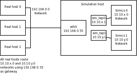
Figure 2. Example setup of multiple Simics instances using
a host connection
Figure 3 shows a setup similar to Figure 2. In
this case the target machine connect to the real network using an Ethernet
bridge on the simulation host. The bridge is invisible to both the target
machines and the real hosts. As all IP addresses must be on the 192.168.0.0
network, the Simics 0 configuration uses IP addresses between 192.168.0.0 and
192.168.0.9, and the Simics 1 configuration uses IP addresses between
192.168.0.10 and 192.168.0.19. Note that both sim_tap0 and sim_tap1 are part
of the same Ethernet bridge, and that none of the interfaces that are a part of
the bridge has any IP address. In this description the MAC addresses have been
left out to not unnecessarily clutter the figure and description. These needs to
be partitioned between the two Simics configurations in the same way as the IP
addresses.
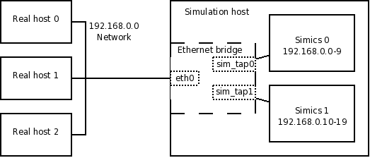
Figure 3. Example setup of multiple Simics instances
using a bridged connection
When connecting to a real network on a host with multiple network interfaces
installed, Simics will select one of them for the real network connection. If
the default selection is incorrect, all commands have an interface argument to
select the desired interface. The interface name expected by the interface
argument is the ordinary interface name used by the host operating system. The
next two sections describe how to obtain the names of the simulation host’s
network interfaces for Linux and Windows hosts.
All network interfaces are listed by /sbin/ifconfig -a on the simulation host:
computer$ /sbin/ifconfig -a
eth0      Link encap:Ethernet  HWaddr 00:10:18:0A:DE:EF
          BROADCAST MULTICAST  MTU:1500  Metric:1
          RX packets:0 errors:0 dropped:0 overruns:0 frame:0
          TX packets:0 errors:0 dropped:0 overruns:0 carrier:0
          collisions:0 txqueuelen:1000
          RX bytes:0 (0.0 b)  TX bytes:0 (0.0 b)
          Interrupt:21

eth1      Link encap:Ethernet  HWaddr 00:0C:F1:D1:FF:09
          inet addr:10.0.0.140  Bcast:10.0.0.255  Mask:255.255.255.0
          UP BROADCAST RUNNING MULTICAST  MTU:1500  Metric:1
          RX packets:671467287 errors:0 dropped:0 overruns:0 frame:0
          TX packets:647635204 errors:0 dropped:0 overruns:0 carrier:0
          collisions:0 txqueuelen:1000
          RX bytes:3725791210 (3553.1 Mb)  TX bytes:217046405 (206.9 Mb)
          Interrupt:20 Base address:0xdf40 Memory:fceef000-fceef038

lo        Link encap:Local Loopback
          inet addr:127.0.0.1  Mask:255.0.0.0
          UP LOOPBACK RUNNING  MTU:16436  Metric:1
          RX packets:24929 errors:0 dropped:0 overruns:0 frame:0
          TX packets:24929 errors:0 dropped:0 overruns:0 carrier:0
          collisions:0 txqueuelen:0
          RX bytes:4164218 (3.9 Mb)  TX bytes:4164218 (3.9 Mb)
For example, to use the first interface listed above, specify eth0 as the
interface argument.
The interface name expected by the interface argument is the ordinary
interface name used by the host operating system. All interfaces of the host are
listed in the Network Connections folder in the Control Panel;
alternatively, ipconfig can be used in a command prompt on the simulation
host:
C:\> ipconfig

Windows IP Configuration


Ethernet adapter Local Area Connection:

   Connection-specific DNS Suffix  . :
   IP Address. . . . . . . . . . . . : 10.0.0.191
   Subnet Mask . . . . . . . . . . . : 255.255.255.0
   Default Gateway . . . . . . . . . : 10.0.0.3

Ethernet adapter LAB:

   Connection-specific DNS Suffix  . :
   IP Address. . . . . . . . . . . . : 10.10.0.1
   Subnet Mask . . . . . . . . . . . : 255.255.255.0
   Default Gateway . . . . . . . . . :

Ethernet adapter TAP:

   Media State . . . . . . . . . . . : Media disconnected
For example, to use the first interface listed above, specify “Local Area
Connection” as the interface argument. There is no need to specify the entire
interface name: it is enough to specify a unique substring.
When using other connection types than port forwarding, Simics has to prevent
the simulated network from being flooded with packets from the real network. In
practice, the simulated machine is not always able to handle the amount of
traffic it receives, and Simics cannot buffer all incoming packets. This is
especially a problem when the simulation is stopped.
Flooding is prevented by limiting the amount of traffic that is allowed to enter
the simulated network per simulated second. This amount is determined by the
tx_bandwidth and tx_packet_rate attributes of the real network object
created for the connection, typically named real_net0. The unit of the
tx_bandwidth attribute is bits per simulated second, and the unit of the
tx_packet_rate attribute is packets per simulated second. Either can be set to
unlimited by setting them to 0, but this is not recommended unless a very
limited amount of data is to be received. The default is to allow 10 megabits
per simulated second and an unlimited number of packets.
In addition to allowing the selected rate of traffic into the simulated network,
Simics buffers traffic for an additional 0.1 seconds of simulated time, to avoid
dropping packets during a short peak in the traffic. If more packets arrive once
this buffer is full, Simics will drop them.
To get better performance out of the connection to the real network, modify the
value of the tx_bandwidth and tx_packet_rate attributes until satisfied. A
good strategy is to set the tx_bandwidth attribute to the amount of traffic
that the simulated machine is expected to handle per simulated second, and then
try to increase the tx_packet_rate from about 5000 and see at what packet rate
the best performance is achieved.
For example, this will set the limit to 100 megabits and 10000 packets per
simulated second:
simics> @conf.real_net0.tx_bandwidth = 100000000
simics> @conf.real_net0.tx_packet_rate = 10000
A network monitoring tool such as Wireshark (formerly known as Ethereal) is
invaluable when debugging problems with the real network connections. It is a
graphical traffic analyzer that can analyze most common network protocols.
Wireshark is available from
http://www.wireshark.com.
There are some pitfalls one might encounter when trying to connect a simulated
network to a real one:
- Trying to access the simulation host Accessing the
simulation host from the simulated network, or the other way around, is only
supported with port forwarding and host connection. It is difficult—sometimes
impossible—to access the simulation host from the simulated network when
setting up an Ethernet bridging connection.
- Simulated OS has no route When using a NAPT
connection and the operating system of the simulated machine does not have a
correct route to the real network, the simulated machine will drop the packets
or send them to the wrong address. To view the routing setup on the simulated
machine, use the command
netstat -r on Linux or route print on Windows.
Note that these commands should be executed on the simulated machines. The
simulated OS should have a default route to the service node.
- Simics uses the wrong host network interface On a
host with multiple network interfaces installed, Simics will only use one of
them for a real network connection. If the default selection is incorrect, use
the interface argument of the connect command to select the desired network
interface. See the previous section Selecting Host Ethernet
Interface.