Design and architecture
Architecture and Operation
The PMEM-CSI driver can operate in two different device modes: LVM and direct. This table contains an overview and comparison of those modes. There is a more detailed explanation in the following paragraphs.
LVM |
direct |
|
|---|---|---|
| Main advantage | avoids free space fragmentation1 | simpler, somewhat faster, but free space may get fragmented1 |
| What is served | LVM logical volume | pmem block device |
| Region affinity2 | yes: one LVM volume group is created per region, and a volume has to be in one volume group | yes: namespace can belong to one region only |
| Namespace modes | fsdax mode3 namespaces pre-created as pools |
namespace in fsdax mode created directly, no need to pre-create pools |
| Limiting space usage | can leave part of device unused during pools creation | no limits, creates namespaces on device until runs out of space |
| Name field in namespace | Name gets set to 'pmem-csi' to achieve own vs. foreign marking | Name gets set to VolumeID, without attempting own vs. foreign marking |
| Minimum volume size | 4 MB | 1 GB (see also alignment adjustment below) |
| Alignment requirements | LVM creation aligns size up to next 4MB boundary | driver aligns size up to next alignment boundary. The default alignment step is 1 GB. Device(s) in interleaved mode will require larger minimum as size has to be at least one alignment step. The possibly bigger alignment step is calculated as interleave-set-size multiplied by 1 GB |
| Huge pages supported4 | maybe | yes |
1 Free space fragmentation is a problem when there appears to be enough free capacity for a new namespace, but there isn’t a contiguous region big enough to allocate it. The PMEM-CSI driver is only capable of allocating continguous memory to a namespace and cannot de-fragment or combine smaller blocks. For example, this could happen when you create a 63 GB namespace, followed by a 1 GB namespace, and then delete the 63 GB namespace. Eventhough there is 127 GB available, the driver cannot create a namespace larger than 64 GB.
---------------------------------------------------------------------
|         63 GB free         | 1GB used |         64 GB free        |
---------------------------------------------------------------------
2 Region affinity means that all parts of a provisioned file system are physically located on device(s) that belong to same PMEM region. This is important on multi-socket systems where media access time may vary based on where the storage device(s) are physically attached.
3 fsdax mode is required for NVDIMM
namespaces. See Persistent Memory
Programming for
details. devdax mode is not supported. Though a
raw block volume would be useful when a filesystem isn’t needed, Kubernetes
cannot handle binding a character device to a loop device.
4 Huge pages supported: ext4 and XFS filesystems are created using the options that should enable huge page support, as explained in section “Verifying IO Alignment” in “Using Persistent Memory Devices with the Linux Device Mapper”. Testing that support by observing page faults confirmed that this worked for direct mode. It did not work for LVM mode in the QEMU virtual machines, but it cannot be ruled out that it works elsewhere.
LVM device mode
In Logical Volume Management (LVM) mode the PMEM-CSI driver uses LVM for logical volume Management to avoid the risk of fragmentation. The LVM logical volumes are served to satisfy API requests. There is one volume group created per region, ensuring the region-affinity of served volumes.
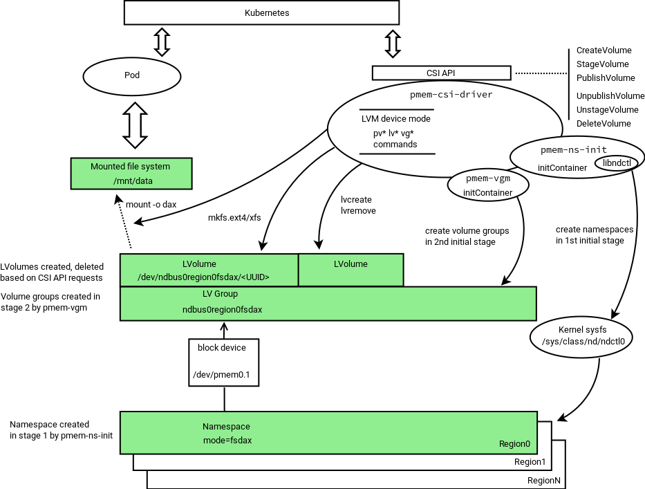
During startup, the driver scans persistent memory for regions and namespaces, and tries to create more namespaces using all or part (selectable via option) of the remaining available space. Later it arranges physical volumes provided by namespaces into LVM volume groups.
Namespace modes in LVM device mode
The PMEM-CSI driver pre-creates namespaces in fsdax mode forming
the corresponding LVM volume group. The amount of space to be
used is determined using the option -pmemPercentage given to pmem-csi-driver.
This options specifies an integer presenting limit as percentage.
The default value is 100.
Using limited amount of total space in LVM device mode
The PMEM-CSI driver can leave space on devices for others, and
recognize “own” namespaces. Leaving space for others can be achieved
by specifying lower-than-100 value to -pmemPercentage option.
The distinction “own” vs. “foreign” is
implemented by setting the Name field in namespace to a static
string “pmem-csi” during namespace creation. When adding physical
volumes to volume groups, only those physical volumes that are based on
namespaces with the name “pmem-csi” are considered.
Direct device mode
The following diagram illustrates the operation in Direct device mode:
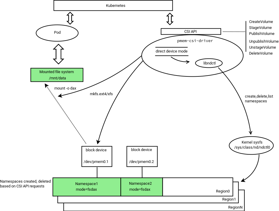
In direct device mode PMEM-CSI driver allocates namespaces directly from the storage device. This creates device space fragmentation risk, but reduces complexity and run-time overhead by avoiding additional device mapping layer. Direct mode also ensures the region-affinity of served volumes, because provisioned volume can belong to one region only.
Namespace modes in direct device mode
The PMEM-CSI driver creates a namespace directly in the mode which is asked by volume creation request, thus bypassing the complexity of pre-allocated pools that are used in LVM device mode.
Using limited amount of total space in direct device mode
In direct device mode, the driver does not attempt to limit space use. It also does not mark “own” namespaces. The Name field of a namespace gets value of the VolumeID.
Kata Containers support
Kata Containers runs applications inside a virtual machine. This poses a problem for App Direct mode, because access to the filesystem prepared by PMEM-CSI is provided inside the virtual machine by the 9p or virtio-fs filesystems. Both do not support App Direct mode:
9p does not support
mmapat all.virtio-fs only supports it when not using
MAP_SYNC, i.e. without dax semantic.
This gets solved as follows:
PMEM-CSI creates a volume as usual, either in direct mode or LVM mode.
Inside that volume it sets up an ext4 or xfs filesystem.
Inside that filesystem it creates a
pmem-csi-vm.imgfile that contains partition tables, dax metadata and a partition that takes up most of the space available in the volume.That partition is bound to a
/dev/loopdevice and the formatted with the requested filesystem type for the volume.When an application needs access to the volume, PMEM-CSI mounts that
/dev/loopdevice.An application not running under Kata Containers then uses that filesystem normally but due to limitations in the Linux kernel, mounting might have to be done without
-odaxand thus App Direct access does not work.When the Kata Containers runtime is asked to provide access to that filesystem, it will instead pass the underlying
pmem-csi-vm.imgfile into QEMU as a nvdimm device and inside the VM mount the/dev/pmem0p1partition that the Linux kernel sets up based on the dax meta data that was placed in the file by PMEM-CSI. Inside the VM, the App Direct semantic is fully supported.
Such volumes can be used with full dax semantic only inside Kata Containers. They are still usable with other runtimes, just not with dax semantic. Because of that and the additional space overhead, Kata Containers support has to be enabled explicitly via a storage class parameter and Kata Containers must be set up appropriately.
Dynamic provisioning of local volumes
Traditionally, Kubernetes expects that a driver deployment has a
central component, usually implemented with the external-provisioner
and a custom CSI driver component which implements volume creation.
That central component is hard to implement for a CSI driver that
creates volumes locally on a node.
PMEM-CSI solves this problem by deploying external-provisioner
alongside each node driver and enabling “distributed
provisioning”:
For volumes with storage classes that use late binding (aka “wait for first consumer”), a volume is tentatively assigned to a node before creating it, in which case the
external-provisionerrunning on that node can tell that it is responsible for provisioning.The scheduler extensions help the scheduler with picking nodes where volumes can be created. Without them, the risk of choosing nodes without PMEM may be too high and manual pod scheduling may be needed to avoid long delays when starting pods. Starting with Kubernetes 1.21, storage capacity tracking is used to solve this problem and the scheduler extensions are not needed anymore.
For volumes with storage classes that use immediate binding, the different
external-provisionerinstances compete with each for ownership of the volume by setting the “selected node” annotation. Delays are used to avoid the thundering herd problem. Once a node has been selected, provisioning continues as with late binding. This is less efficient and therefore “late binding” is the recommended binding mode. The advantage is that this mode does not depend on scheduler extensions to put pods onto nodes with PMEM because once a volume has been created, the pod will automatically run on the node of the volume. The downside is that a volume might have been created on a node which has insufficient RAM and CPU resources for a pod.
PMEM-CSI also has a central component which implements the scheduler extender webhook. That component needs to know on which nodes the PMEM-CSI driver is running and how much capacity is available there. This information is retrieved by dynamically discovering PMEM-CSI pods and connecting to their metrics endpoint.
Communication between components
The following diagram illustrates the communication channels between driver components:
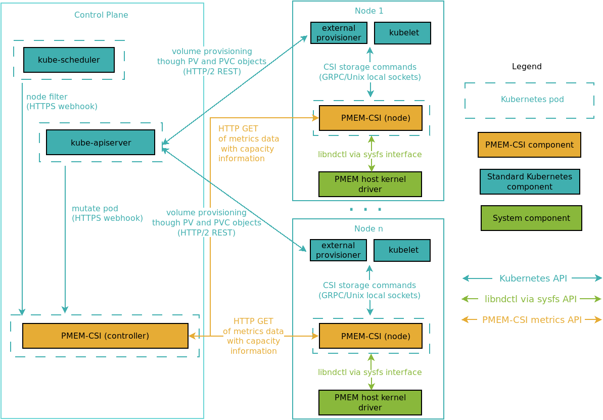
Security
The data exposed via the metrics endpoint is not considered confidential and therefore offered without access control via HTTP. This also simplifies scraping that data with tools like Prometheus.
The communication between Kubernetes and the scheduler extender webhook is protected by TLS because this is encouraged and supported by Kubernetes. But as the webhook only exposes information that is already available, it accepts all incoming connection without checking the client certificate.
The test/setup-ca.sh
script shows how to generate self-signed certificates. The test cluster is set
up using certificates created by that script, with secrets prepared by
test/setup-deployment.sh before
deploying the driver using the provided deployment files.
Beware that these are just examples. Administrators of a cluster must ensure that they choose key lengths and algorithms of sufficient strength for their purposes and manage certificate distribution.
A production deployment can improve upon that by using some other key delivery mechanism, like for example Vault.
The PMEM-CSI controller runs with the default security context. On upstream Kubernetes, this means that it runs as root. The expectation is that actual production deployments of PMEM-CSI will avoid that, for example with the help of OpenShift’s dynamid UID assignment.
The PMEM-CSI node driver must run as root because it has to access the
node’s /dev and /sys and needs to execute privileged operations
like mounting.
Volume Persistency
In a typical CSI deployment, volumes are provided by a storage backend that is independent of a particular node. When a node goes offline, the volume can be mounted elsewhere. But PMEM volumes are local to node and thus can only be used on the node where they were created. This means the applications using PMEM volume cannot freely move between nodes. This limitation needs to be considered when designing and deploying applications that are to use local storage.
These are the volume persistency models considered for implementation in PMEM-CSI to serve different application use cases:
Persistent volumes
A volume gets created independently of the application, on some node where there is enough free space. Applications using such a volume are then forced to run on that node and cannot run when the node is down. Data is retained until the volume gets deleted.Ephemeral volumes
Each time an application starts to run on a node, a new volume is created for it on that node. When the application stops, the volume is deleted. The volume cannot be shared with other applications. Data on this volume is retained only while the application runs.
| Volume | Kubernetes | PMEM-CSI | Limitations |
|---|---|---|---|
| Persistent | supported | supported | topology aware scheduling1 |
| Ephemeral | supported2 | supported | resource constraints3 |
1 Topology aware scheduling ensures that an application runs on a node where the volume was created. For CSI-based drivers like PMEM-CSI, Kubernetes >= 1.13 is needed. On older Kubernetes releases, pods must be scheduled manually onto the right node(s).
2 CSI ephemeral volumes feature support is alpha in Kubernetes v1.15, and beta in v1.16.
3 The upstream design for CSI ephemeral volumes does not take resource constraints into account. If an application gets scheduled onto a node and then creating the ephemeral volume on that node fails, the application on the node cannot start until resources become available. This will be solved with generic ephemeral volumes which are an alpha feature in Kubernetes 1.19 and supported by PMEM-CSI because they use the normal volume provisioning process.
See volume parameters for configuration information.
Volume Size
The size of a volume reflects how much of the underlying storage that is managed by PMEM-CSI is required for the volume. That size is also what needs to be specified when requesting a volume.
For LVM, the number of blocks taken away from a volume group is the
same as the number of blocks in the new logical volume. For direct
mode, there is some additional
overhead. PMEM-CSI
stores the additional meta data on the PMEM device (--map=dev in
ndctl) because that way, volumes can be used without affecting the
available DRAM on a node. The size of a namespace as listed by ndctl
refers to the usable size in the block device for the namespace, which
is less than the amount of PMEM reserved for the namespace in the
region and thus also less than the requested volume size.
In both modes, the filesystem created on the block device introduces further overhead. The overhead for the filesystem and the additional meta data in direct mode is something that users must consider when deploying applications.
Note: Applications can request to map a file into memory that is too
large for the filesystem. Attempts to actually use all of the mapped
file then will lead to page faults once all available storage is
exhausted. Applications should use fallocate to ensure that this
won’t happen. See the memcached example
YAML
for a way how to deal with this for applications that do not use
fallocate themselves.
Capacity-aware pod scheduling
PMEM-CSI implements the CSI GetCapacity call, but Kubernetes
currently doesn’t call that and schedules pods onto nodes without
being aware of available storage capacity on the nodes. The effect is
that pods using volumes with late binding may get tentatively assigned
to a node and then may have to be rescheduled repeatedly until by
chance they land on a node with enough capacity. Pods using multiple
volumes with immediate binding may be unable to run permanently if
those volumes were created on different nodes.
Storage capacity tracking was added as alpha feature in Kubernetes 1.19 to enhance support for pod scheduling with late binding of volumes.
Until that feature becomes generally available, PMEM-CSI provides two components that help with pod scheduling:
Scheduler extender
When a pod requests a special extended resource , the Kubernetes scheduler calls a scheduler extender provided by PMEM-CSI with a list of nodes that a pod might run on.
The name of that special resource is <CSI driver name>/scheduler,
i.e. pmem-csi.intel.com/scheduler when the default PMEM-CSI driver
name is used. It is possible to configure one extender per PMEM-CSI
deployment because each deployment has its own unique driver name.
This extender is implemented in the PMEM-CSI controller and retrieves metrics data from each PMEM-CSI node driver instance to filter out all nodes which currently do not have enough storage left for the volumes that still need to be created. This considers inline ephemeral volumes and all unbound volumes, regardless whether they use late binding or immediate binding.
This special scheduling can be requested manually by adding this snippet to one container in the pod spec:
containers:
- name: some-container
  ...
  resources:
    limits:
      pmem-csi.intel.com/scheduler: "1"
    requests:
      pmem-csi.intel.com/scheduler: "1"
This scheduler extender is optional and not necessarily installed in all clusters that have PMEM-CSI. Don’t add this extended resource unless the scheduler extender is installed, otherwise the pod won’t start!
See our implementation of a scheduler extender.
Pod admission webhook
Having to add the <CSI driver name>/scheduler extended resource manually is not
user-friendly. To simplify this, PMEM-CSI provides a mutating
admission
webhook
which intercepts the creation of all pods. If that pod uses inline
ephemeral volumes or volumes with late binding that are provided by
PMEM-CSI, the webhook transparently adds the extended resource
request. PMEM-CSI volumes with immediate binding are ignored because
for those the normal topology support ensures that unsuitable nodes
are filtered out.
The webhook can only do that if the persistent volume claim (PVC) and its storage class have been created already. This is normally not required: it’s okay to create the pod first, then later add the PVC. The pod simply won’t start in the meantime.
The webhook deals with this uncertainty by allowing the creation of the pod without adding the extended resource when it lacks the necessary information. The alternative would be to reject the pod, but that would be a change of behavior of the cluster that may affect also pods that don’t use PMEM-CSI at all.
Users must take care to create PVCs first, then the pods if they want to use the webhook. In practice, that is often already done because it is more natural, so it is not a big limitation.
PMEM-CSI Operator
PMEM-CSI operator facilitates deploying and managing the PMEM-CSI driver on a Kubernetes cluster. This operator is based on the CoreOS operator-sdk tools and APIs.
The driver deployment is controlled by a cluster-scoped custom resource
named PmemCSIDeployment in the
pmem-csi.intel.com/v1beta1 API group. The operator runs inside the cluster
and listens for deployment changes. It makes sure that the required Kubernetes
objects are created for a driver deployment. Refer to the PmemCSIDeployment
CRD for details.